Receiver
| Documentation | /NGOS | /Signals | /Shells | /Cmds | /Ctrl | /HALs | /Conf | /Params | /Behaviors | /Receiver | /GPS | Next Chapter |
The NG Receiver Support
Overview
The following list shows the supported RC-receivers and protocols:
| Brand | Protocol | Type | FC support | RC controller | HW.uart[X] | ||||
| Version | HW.uart[X].mode | RC.dev.[p|s] | Version | RC.dev.[X] | .format | .baudrate | |||
| - | Sum signal | analog | beginning | auto | rcsum | beginning | rccsum | - | - |
| ACT | DSL | digital | 0.41 | auto | uart[x] | 0.54 | dsl[x] | 8N1 | 38400 |
| ACT | S3D | analog | 0.54 | auto | rcsumS3D | n/a | - | - | |
| ACT | S3D | digital | 0.59 | auto | uart[x] | 0.59 | dsl[x] | 8N1 | 38400 |
| FrSky | S-Bus | digital | 0.69 | frsky | uart[x] | n/a | 8E2 | 100000 | |
| Futaba | S.Bus | digital | 0.64-0.68 | auto | uart[x] | 0.68 | sbus[x] | 8E2 | 100000 |
| Futaba | S.Bus | digital | 0.69 | futaba | uart[x] | 0.68 | sbus[x] | 8E2 | 100000 |
| Graupner | HoTT SUMD | digital | 0.66 | auto | uart[x] | n/a | 8N1 | 115200 | |
| Multiplex | M-Link | digital | n/a | auto | uart[x] | 0.60 | dsl[x] | 8N1 | 38400 |
| Spektrum | digital | 0.63 | spektrum | uart[x] | n/a | 8N1 | 115200 | ||
Supported telemetry protocols:
| Brand | Protocol | Type | FC support | HW.uart[X] | ||
| Version | .format | .baudrate | .mode | |||
| Multiplex / ACT | MSB / M-Bus | digital | 0.64 | 8N1 | 38400 | msb |
| Graupner | HoTTv4 (Telemetry) | digital | 0.68 | 8N1 | 19200 | hott |
ACT DSL Receiver
ACT produces great cheap and expensive PPM, PCM, SPCM and 2.4GHz receivers with and without Telemetry support and most of them have a DSL interface.
The NG firmware is now able to understand the proprietary DSL and S3D DSL protocols of the RC receivers from ACT as well as the open M-Bus (MSB) Telemetry protocol supported by the telemetry receivers from ACT. This allows us to connect any receiver with a DSL interface or M-Bus interface to the NG.
Example of an ACT receiver port for the DSL protocol.
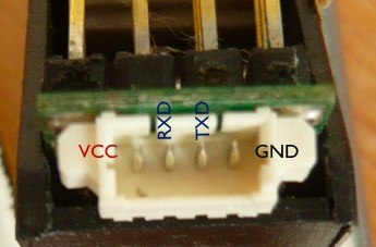
The connections have to be wired straigth (not crossed).
Besides the above the NG allows you to connect an ordinary receiver with analog sum-signal output or an ACT 4+2XS 2.4GHz sum-signal receiver from ACT.
How to use ACT DSL or ACT S3D DSL
DSL is a simple serial protocol. To support DSL on an UART you simply switch the UART’s baud rate to 38400 baud with the command set HW.uart1.baud 38400. After that, be sure to store the configuration with **conf store **.
# set HW.uart1.baud 38400

Setting integer 'HW.uart1.baud' to '38400'

# conf store

Storing current configuration to slot 0 in flash memory sector 26... succeeded!
Now reset your NG using the reset button, by power-cycling it or by issuing the reboot shell command.
Having configured UART1 to 38400 baud you are now able to connect your DSL receiver to that UART. The NGOS should automatically detect the DSL receiver and it should start to show up when issuing the command show devices similar to this:
# show devices

Detected devices:

  Addr  Bus     Description

  0x52  I2C1    Holger BL-Ctrl (front)
  0x54  I2C1    Holger BL-Ctrl (back)
  0x56  I2C1    Holger BL-Ctrl (right)
  0x58  I2C1    Holger BL-Ctrl (left)
  0x00  ADC0    ADXRS MEMS Gyroscope (nick)
  0x01  ADC0    ADXRS MEMS Gyroscope (roll)
  0x02  ADC0    ADXRS MEMS Gyroscope (yaw)
  0x00  SPI0    LIS3LV02DQ 3-Axis Accelerometer
  0x00  UART1   ACT DSL Receiver
You should be able to check the DSL receiver’s status with the command print dsl status:
# print dsl status

DSL statistic on uart0:

    Signal quality:     0
    Battery:            0
    Band:               0

    Channel:            0

    Invalid packets:    0
    Unknown packets:    0

    Status packets:     0
    Signal packets:     0

DSL statistic on uart1:

    Signal quality:     100
    Battery:            156
    Band:               35

    Channel:            20

    Invalid packets:    0
    Unknown packets:    0

    Status packets:     146303
    Signal packets:     11340
You should also be able to see the received with the command print dsl channels:
# print dsl channels

DSL Parser on uart0:

    Signal quality:     0
    Battery:            0
    Channel:            0

    -C00- -C01- -C02- -C03- -C04- -C05- -C06- -C07- -C08- -C09- -C10- -C11-
     N/A   N/A   N/A   N/A   N/A   N/A   N/A   N/A   N/A   N/A   N/A   N/A

DSL Parser on uart1:

    Signal quality:     100
    Battery:            156
    Channel:            35

    -C00- -C01- -C02- -C03- -C04- -C05- -C06- -C07- -C08- -C09- -C10- -C11-
    -127  -002  +000  +000  -123  -128  -097  -108  -121  -122  +000  +000
{i} This is not always the signal that the closed-loop controllers will receive! What they receive depends on the configuration of the global variables RC.dev.mix, RC.dev.primary and RC.dev.secondary.
How to handle RC devices
Primary and Seconday RC Devices
To to be able to define the different mix-modes, a primary and secondary RC device need to be defined. The global variable RC.dev.primary and RC.dev.secondary define the devices used. Both of them can have the values rcsum, uart0 and uart1. Here uart0 and uart1 represent DSL receivers connected to UART0 or UART1.
. {{{
set RC.dev.primary dsl0
Setting device in ‘RC.dev.primary’ to ‘4’
set RC.dev.secondary dsl1
Setting device in ‘RC.dev.secondary’ to ‘5’ }}}
RC Mix Mode
The global variable RC.dev.mix defines the RC device mix-mode used. It has thee possible values primary, secondary, ts-mix, ts-switch and diversity.
# set RC.dev.mix primary

Setting RC mix mode in 'RC.dev.mix' to '0'
Mix Mode: primary / secondary
In mix-mode primary the primary RC device defined by RC.dev.primary gets used for control. In mix-mode seconday the secondary RC device defined by RC.dev.secondary gets used for control.
Mix Mode: ts-switch
In mix-mode ts-switch the primary device defined by RC.dev.primary gets used first which is the teacher control. As soon as the behavior action rc.trainer.mode(0) gets triggered by a behavior condition, control gets switched to the secondary device defined by RC.dev.secondary. Now the student has control. As soon as the behavior action rc.trainer.mode(1) gets triggered by a behavior condition on the teacher’s control, control gets switched back to the the teacher and his primary device defined by RC.dev.primary.
Mix Mode: ts-mix
In mix-mode ts-mix the primary device defined by RC.dev.primary and the secondary device defined by RC.dev.secondary get mixed continuously together to one control signal when gets used.
Mix Mode: diversity
Mix-mode diversity is possible when using two DSL receivers only. Only DSL receivers allow to know the signal quality of each received signal, which makes diversity possible. The control signal gets built from the cumulative signal of the two DSL receivers.
LED Blink-Codes
see Signals section
How to use MSB-Telemetry
Introduction
 MSB (or M-Bus in ACT-Terms) is a bus system specified by the R/C-System producer Multiplex (used in their M-Link products). Since it’s a Bus System, you can attach several different sensor devices to the same electrical circuit. In the case when an NG is used in a MSB bus system, NGOS can be configured which MSB addresses to use and which to leave free.
Should an external sensor be used alongside the NG on the same bus, then the address of that external sensor has to be left free in NGOS, or the two will collide while trying to answer the same address!
Full NGOS support for MSB is available since NGOS-0.64.
The NG/M-Bus Cable
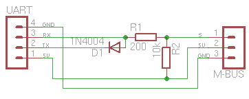
To attach your receivers MSB to your NG you need to build a cable. The cable connects the TX/RX lines of an UART to to single wire needed for the MSB.
Such a NG/MSB Cable is built like this:
Preparing NGOS for MSB Telemetry
NGOS can not automatically detect baud rate and M-Bus activity. Because of that you need to configure your UART you want to use for 38400 baud and for M-Bus usage. This is done like this:
# set HW.uart1.baud 38400

Setting integer 'HW.uart1.baud' to '38400'

# set HW.uart1.mode msb

Setting 'HW.uart1.mode' to uart-mode '2'

# conf store

Storing current configuration to slot 0 in flash memory sector 26... succeded!

# reboot

Rebooting system...
When your NGOS has finished rebooting, attach the receiver using the above NG/M-Bus cable to the choosen UART (UART1 in the above example). Eventually your NG will reboot a second time when attaching the receiver as they sometime use too much power while powering up which reboots the FC.
Afterwards you can check if your NGOS correctly sees and uses the M-Bus/MSB/M-Link interface. You should see the M-Bus/MSB/M-Link parser as running task and you see the M-Bus/MSB/M-Link in the device table.
 # ps

  PID TTY         STATE    DESC
    0 /dev/usb    ready    Terminal Task
    1 /dev/uart0  running  Terminal Task
    2 /dev/uart1  waiting  Terminal Task
    3 /dev/uart1  ready    M-Link/MSB/M-Bus Parser

# show devices

Detected devices:

  Addr  Bus     Description

  0x16  I2C0    Atmel 644P RC/Comm Controller
  0x18  I2C0    Atmel 328P SB Controller
  0x02  ADC12   ADXR/MLX MEMS Gyroscope 12bit (nick)
  0x01  ADC12   ADXR/MLX MEMS Gyroscope 12bit (roll)
  0x00  ADC12   ADXR/MLX MEMS Gyroscope 12bit (yaw)
  0x00  SPI0    LIS3LV02DQ 3-Axis Accelerometer
  0x03  SPI0    AD7924 12bit Analog Digital Converter
  0x02  UART1   M-Link/MSB/M-Bus Telemetry
  0x00  SBCTRL  MicroMag 3 Magnetic Compass (calibrated)
Configuring the available M-Bus Sensor Slots
Next you need to configure what sensor data you want to see in which sensor slot. By default all slots are free.
# show mbus

Current system configuration:

  MBUS.sensor2      free                M-Bus/MSB/M-Link Sensor Slot 2
  MBUS.sensor3      free                M-Bus/MSB/M-Link Sensor Slot 3
  MBUS.sensor4      free                M-Bus/MSB/M-Link Sensor Slot 4
  MBUS.sensor5      free                M-Bus/MSB/M-Link Sensor Slot 5
  MBUS.sensor6      free                M-Bus/MSB/M-Link Sensor Slot 6
  MBUS.sensor7      free                M-Bus/MSB/M-Link Sensor Slot 7
  MBUS.sensor8      free                M-Bus/MSB/M-Link Sensor Slot 8
  MBUS.sensor9      free                M-Bus/MSB/M-Link Sensor Slot 9
  MBUS.sensor10     free                M-Bus/MSB/M-Link Sensor Slot 10
  MBUS.sensor11     free                M-Bus/MSB/M-Link Sensor Slot 11
  MBUS.sensor12     free                M-Bus/MSB/M-Link Sensor Slot 12
  MBUS.sensor13     free                M-Bus/MSB/M-Link Sensor Slot 13
  MBUS.sensor14     free                M-Bus/MSB/M-Link Sensor Slot 14
  MBUS.sensor15     free                M-Bus/MSB/M-Link Sensor Slot 15
You can configure each M-Bus/MSB/M-Link sensor slot to contain an arbitrary data value. To see all available data values issue a set command:
 # set MBUS.sensor2 ?

Input validation failed! Please use one of the following sensor types:

        free
        battery
        N
        R
        Y
        compass
        height
        gps_lon
        gps_lat
        gps_speed
        pos_lon
        pos_lat
        home_lon
        home_lat
        target_lon
        target_lat
        target_distance
        target_deviation
        navN
        navR
        navY
        dbg1
        dbg2
        dbg3
        dbg4
You can then configure the available slots as you like:
# set MBUS.sensor2 battery

Configured M-Bus sensor slot '1' to sensor type 'battery'
Setting 'MBUS.sensor2' to sensor type '1'

# set MBUS.sensor3 N

Configured M-Bus sensor slot '2' to sensor type 'N'
Setting 'MBUS.sensor3' to sensor type '2'

# set MBUS.sensor4 R

Configured M-Bus sensor slot '3' to sensor type 'R'
Setting 'MBUS.sensor4' to sensor type '3'

# set MBUS.sensor5 Y

Configured M-Bus sensor slot '4' to sensor type 'Y'
Setting 'MBUS.sensor5' to sensor type '4'
Afterwards check your M-Bus/MSB/M-Link sensor slot definitions and store them:
# show mbus

Current system configuration:

  MBUS.sensor2      battery             M-Bus/MSB/M-Link Sensor Slot 2
  MBUS.sensor3      N                   M-Bus/MSB/M-Link Sensor Slot 3
  MBUS.sensor4      R                   M-Bus/MSB/M-Link Sensor Slot 4
  MBUS.sensor5      Y                   M-Bus/MSB/M-Link Sensor Slot 5
  MBUS.sensor6      free                M-Bus/MSB/M-Link Sensor Slot 6
  MBUS.sensor7      free                M-Bus/MSB/M-Link Sensor Slot 7
  MBUS.sensor8      free                M-Bus/MSB/M-Link Sensor Slot 8
  MBUS.sensor9      free                M-Bus/MSB/M-Link Sensor Slot 9
  MBUS.sensor10     free                M-Bus/MSB/M-Link Sensor Slot 10
  MBUS.sensor11     free                M-Bus/MSB/M-Link Sensor Slot 11
  MBUS.sensor12     free                M-Bus/MSB/M-Link Sensor Slot 12
  MBUS.sensor13     free                M-Bus/MSB/M-Link Sensor Slot 13
  MBUS.sensor14     free                M-Bus/MSB/M-Link Sensor Slot 14
  MBUS.sensor15     free                M-Bus/MSB/M-Link Sensor Slot 15

# conf store

Storing current configuration to slot 0 in flash memory sector 26... succeded!
Receiving M-Bus Telemetry on the ground
To receive M-Bus/MSB/M-Link telemetry on the ground you need telemetry hardware.
Multiplex Telemetry
In the case of Multiplex senders, the sender itself can display the received sensor data.
ACT Telemetry
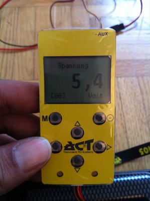
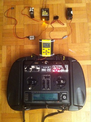
In the case of ACT senders, you can attach a device called UPD to the sender’s S-Bus which will display the received data.
FrSky/Futaba S-Bus receiver support
Note: FrSky receivers are only supported in NGOS 0.69 and later! The following describes how to configure FrSky/Futaba in NGOS 0.69 or later!
Some Futaba and FrSky receivers support the S-Bus protocol. Unfortunately, they map stick positions to channel values differently, and this cannot be autodetected by NGOS, so the type of receiver has to be configured explicitly:
set HW.uart1.baud 100000
set HW.uart1.format 8E2
set HW.uart1.bootmsg yes
set HW.uart1.mode frsky | futaba
set RC.dev.primary uart1
set RC.dev.mix primary
Both types of receivers use active-low signaling, so you will need a signal inverter:
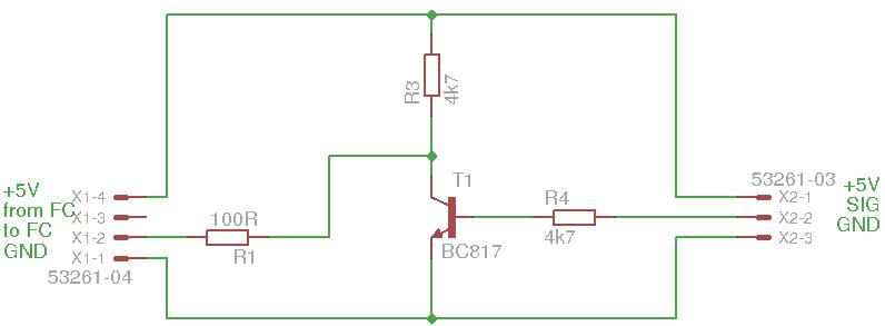
Spektrum Receiver Support
Introduction
The Spektrum receivers (and clones) consist of two types, there’s the main receiver, which has standard servo connectors and a satellite receiver that is plugged into the main receiver for redundancy reasons. NGOS supports the satellite receiver using the serial UARTs on the Flight-Controller out-of-the-box.
Note: 11-bit-precision receivers (dx8, dsmx) work with ngos-0.68+ when the RC.satrxtype parameter is set to 1. With 10-bit-precision receivers, the RC.satrxtype parameter has to be 0.
How to connect the receiver
Prerequisites:
- As of now the satellite receiver needs to be bound to the transceiver before it is connected to the NG-board. That’ll probably change in the future so you can start the bind process from within NGOS.
- NGOS-0.64 or higher
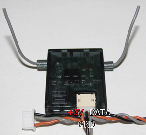
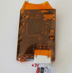
The satellite receiver is connected by 3 wires to the main-receiver - these wires are Ground, Vcc and Data. To connect a satellite receiver the individual pins/wires must be identified - the easiest way to do this is by the color of the wires in the adapter cable. It is usually black for Ground, red for +3V and “other color” for data. If unsure, connect the satellite to the main receiver and use a oscilloscope or logic analyzer to figure out the correct wiring.
After you figured out the wiring and bound the receiver to your transceiver, connect the satellite receiver to one of the UARTs on the FC by connection Ground to UART-Ground, Vcc to UART-Vcc (make sure you soldered your UART to 3.3V, otherwise you’ll fry the satellite receiver) and Data to UART-RX.
Spektrum Satellite receiver
OrangeRx R100 Satellite receiver
How to set it up in NGOS
# set HW.uartX.baud 115200# set HW.uartX.mode spektrum# set RC.dev.primary uartX # set RC.satrxtype 0/1 (0 for 10bit, 1 for 11bit)After this show devices should show the detected spektrum receiver and loop rc will show the channel values. Be sure to set the “travel adjustment” in your transceiver in a way that allows you to get channel values from -2048 to +2048 - otherwise you wont be able to initialize/start your copter.
Note that set RC.satrxtype 0 is standard in NGOS. 11 bit function is only available in NGOS 0.68.
Graupner HOTTv4 telemetry
Prerequisites
- HOTTv4 telemetry support is only available in NGOS >= 0.68.
- All devices (Graupner sender, receiver and smartbox) need to have the same, reasonably recent, firmware. HoTTv4 is required.
- Your sender must support HoTTv4 telemetry. Non-HoTTv4 senders obviously don’t. The “new” (= with voice-alarms) MX-16 HoTT does, whereas the “old” (= without voice-alarms) MX-16 HoTT only supports telemetry if you have a Graupner Smartbox (note that if you’ve got the “old” MX-16 you need the Smartbox anyway to enable the SUM- or SUMD-Signal).
Connecting to your NG
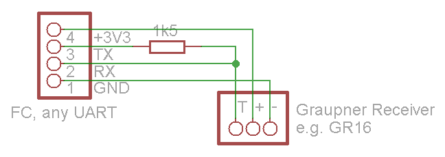
If your receiver is already powered (for example, because you are already using it as a PPM or SUMD receiver), you should leave the “+” pin unconnected.
Otherwise, you’ll have to power the VCC pin on the UART with +3V3 by bridging the appropriate solder jumper (eg. 1-2 of SJ3 on hw-0.24-mini). The receivers seem to be 5V-tolerant, so that should work too.
Configuring NGOS
# set HW.uart1.baud 19200
# set HW.uart1.format 8N1
# set HW.uart1.bootmsg no
# set HW.uart1.mode hott
Verifying that it’s working
If NGOS manages to talk to the receiver, it’ll show up as a detected device in the device table:
# show devices

Detected devices:

  Addr  Bus     Description

  ...
  0x06  UART1   Graupner HoTTv4 Telemetry Transmitter 1
  ...
Using telemetry
Binary Mode
Binary mode is a pre-defined (by Graupner) graphical display with a fixed selection of (for us mostly irrelevant) values.
To enter binary mode, select Model Select -> Airplane,Heli.,Glid. -> Receive+Electronic.
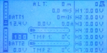
Alternatively, you can select Receive+GPS. The other sensor types are currently not supported.
Text mode
Text mode is actually meant to be used for sensor configuration, but since it can display arbitrary screens of 8x21 characters, it’s rather useful for us. Additionally, it sends keypresses of the four telemetry configuration keys back up – we might later make them accessible via behavior conditions.
Unfortunately, text mode is somewhat hard to reach: select Setting and dataview -> Receive+Electronic and then go to the last page (by repeatedly pressing Enter on the Smartbox or right arrow on the right panel of the new MX-16, until you get to the page that says “UAVP-NG”).
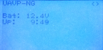
Be aware that one downside of text mode is that there is no (and can be no) signal strength indicator.