NGlight
| Documentation | /NGlight | Next Chapter |
The NGlight
The following describes what you need to start construction of the NGlight light controller board, which can be used to control 16 PWM channels. Each channel has it’s own MOSFET driver which is able to switch 1A.
Getting the needed PCBs
Check out the UAVP-NG Shop to order your NGlight PCBs.
Getting the needed parts
Check out the NGlight part list to find out the components you need to build an NGlight.
Soldering
Solder all parts according to part list.
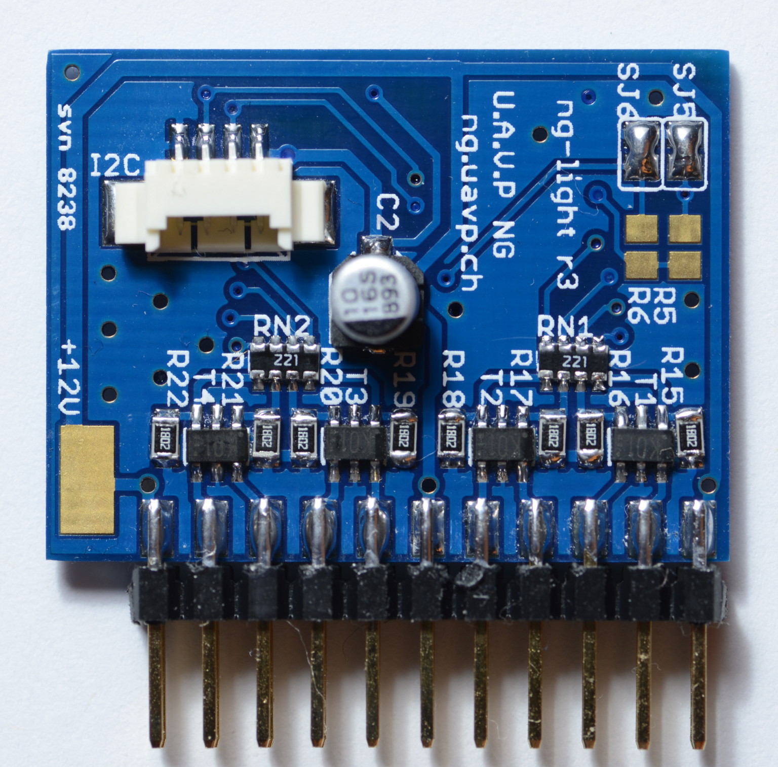 | 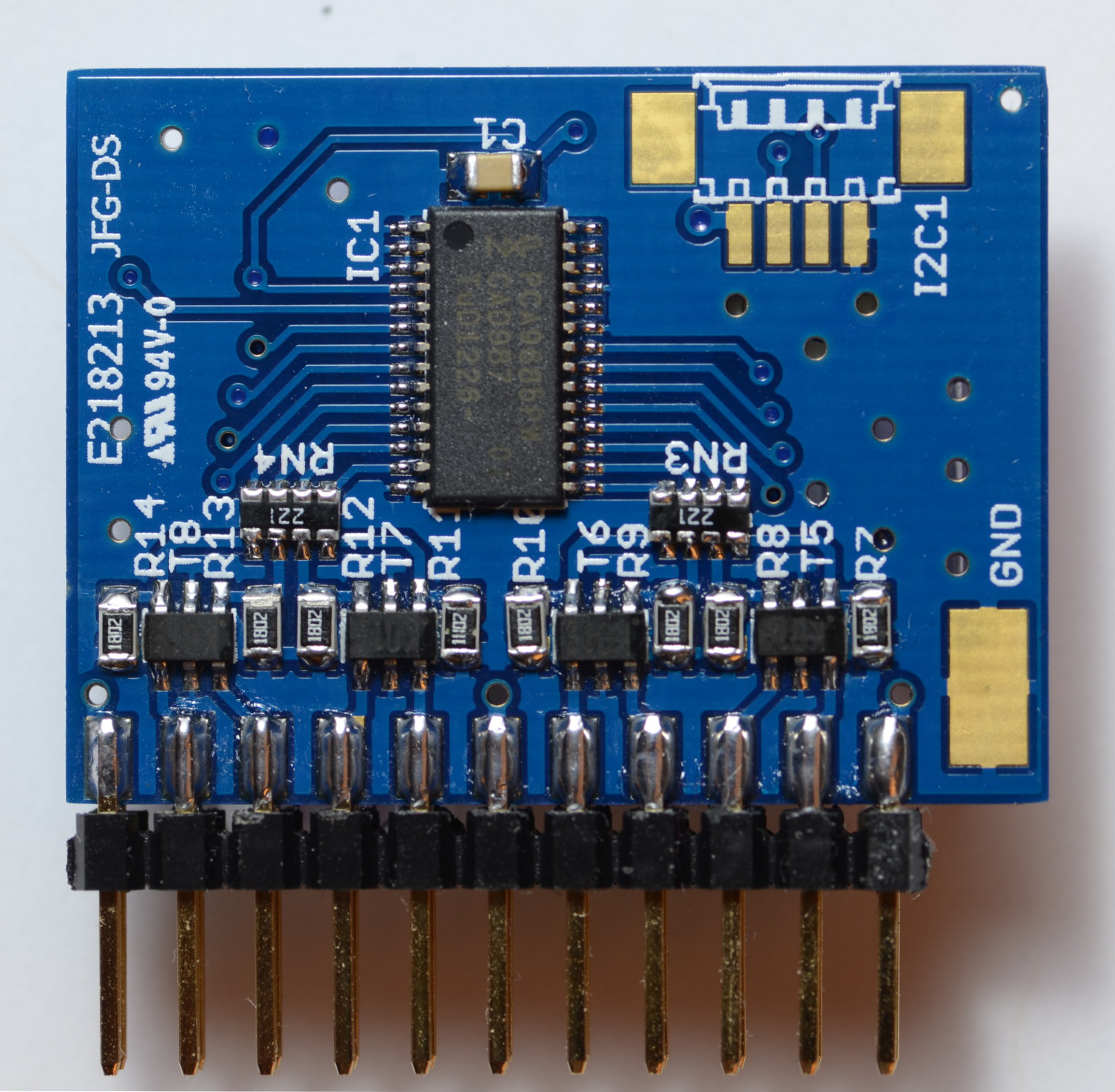 |
Schematic
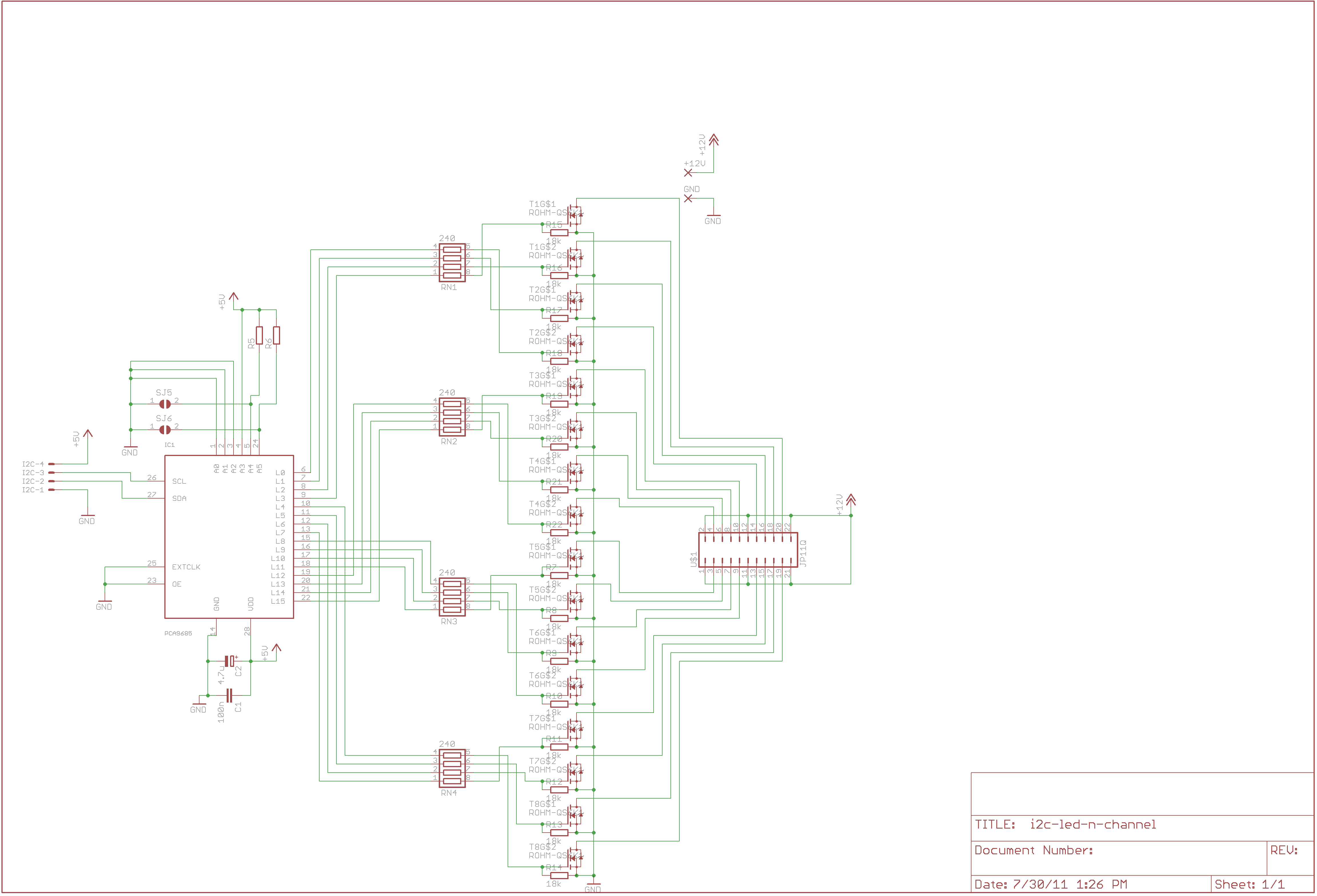
Description of the connectors and jumpers
With the jumpers you can change the I²C address of your NGlight, so that it is possible to use up to four NGlight devices on your NG.
| Add. | SJ5 | SJ6 | R5 | R6 |
| 1 | closed | closed | do not place | do not place |
| 2 | open | closed | 10k | do not place |
| 3 | closed | open | do not place | 10k |
| 4 | open | open | 10k | 10k |
At the current state of development there is just one NGlight device with address 1 supported.
Connecting LEDs
Each channel is an open collector input that switches the input to GND. Connect battery plus - resistor - LED - NGLight input
Connecting the NGlight to a NG
Connect the NGlight to the I²C sensor bus of your NG hardware. You just need 5V or 3.3V, SDA, SDC and ground. After connecting the NGlight, your NG should detect the device automatically.
# show devices

Detected devices:

  Addr  Bus     Description

  0x16  I2C0    Atmel 644P RC/Comm Controller
  0x90  I2C0    PCA9685 Light Controller   <--------------------
  0x52  I2C1    BL-Ctrl Style (Motor 1)
  0x54  I2C1    BL-Ctrl Style (Motor 2)
  0x56  I2C1    BL-Ctrl Style (Motor 3)
  0x58  I2C1    BL-Ctrl Style (Motor 4)
  0x02  ADC12   ADXR/MLX MEMS Gyroscope 12bit (nick)
  0x01  ADC12   ADXR/MLX MEMS Gyroscope 12bit (roll)
  0x00  ADC12   ADXR/MLX MEMS Gyroscope 12bit (yaw)
  0x00  SPI0    LIS3LV02DQ 3-Axis Accelerometer
  0x02  SPI0    ADS1255 24bit Analog Digital Converter
  0x03  SPI0    AD7924 12bit Analog Digital Converter
  0x01  RCCTRL  ACT DSL Receiver DSL0
NGlight configuration parameters
The NGlight has its own configuration section, which controlls the startup value of every single channel.
# show pca

Current PCA configuration:

  PCA.ch0           0                   PCA channel 0 identifier
  PCA.ch1           1                   PCA channel 1 identifier
  PCA.ch2           2                   PCA channel 2 identifier
  PCA.ch3           3                   PCA channel 3 identifier
  PCA.ch4           4                   PCA channel 4 identifier
  PCA.ch5           5                   PCA channel 5 identifier
  PCA.ch6           6                   PCA channel 6 identifier
  PCA.ch7           7                   PCA channel 7 identifier
  PCA.ch8           8                   PCA channel 8 identifier
  PCA.ch9           9                   PCA channel 9 identifier
  PCA.ch10          10                  PCA channel 10 identifier
  PCA.ch11          11                  PCA channel 11 identifier
  PCA.ch12          12                  PCA channel 12 identifier
  PCA.ch13          13                  PCA channel 13 identifier
  PCA.ch14          14                  PCA channel 14 identifier
  PCA.ch15          15                  PCA channel 15 identifier

  PCA.init.ch0      0                   PCA init value ch0
  PCA.init.ch1      0                   PCA init value ch1
  PCA.init.ch2      0                   PCA init value ch2
  PCA.init.ch3      0                   PCA init value ch3
  PCA.init.ch4      0                   PCA init value ch4
  PCA.init.ch5      0                   PCA init value ch5
  PCA.init.ch6      0                   PCA init value ch6
  PCA.init.ch7      0                   PCA init value ch7
  PCA.init.ch8      0                   PCA init value ch8
  PCA.init.ch9      0                   PCA init value ch9
  PCA.init.ch10     0                   PCA init value ch10
  PCA.init.ch11     0                   PCA init value ch11
  PCA.init.ch12     0                   PCA init value ch12
  PCA.init.ch13     0                   PCA init value ch13
  PCA.init.ch14     0                   PCA init value ch14
  PCA.init.ch15     0                   PCA init value ch15
The channel identifiers
With the parameters PCA.ch0 - PCA.ch15 you can assign every physical channel its own identifier, which is used later by the action of a behavior. The really nice thing of the identifiers is, that you can group several physical channels to one virtual identifier. To group the physical channels 0 and 1 just do a..
set PCA.ch0 0 <--just needed if PCA.ch0 wasn't 0
set PCA.ch1 0
Know it is possible to control both channels with the same identifier.
The init values
The parameters PCA.init.ch0 - PCA.init.ch15 controll the start up values of the channels.
Set the PWM duty cycle
There are two ways to set the PWM duty cycle of a channel. On the one hand you can use the internal tune command which is rather for testing purpose and on the other hand you can use some behavior actions for this.
The tune command
With the tune command you can assign a value between 0 - 4095 to a channel group via it’s identifier, where 4095 stands for a 100% duty cycle. The syntax of the tune command is really simple.
tune pca9685 <ch_id> <value>So if we would like to controll our channel group 0 from above, we could use the following command, to turn the physical channels 0 and 1 to 50% duty cycle.
tune pca9685 0 2048The behavior actions
There are four new actions which can be used to control the NGlight
actor.pca9685.set.light(x,y)        set channel  x to duty cycle y  [0..127]
actor.pca9685.dim.light(x,y)        dim channel  x to pot[y]
actor.pca9685.set.scheme(x)         Load scheme x to channels 0-11
actor.pca9685.set.sequence(x,y)     Set sequence y to group x
The last two actions are still not 100% functional (they won’t crash your NG they just doesn’t work correctly in the latest public release ;)) Some sample behaviors could look like this
08  when.rc.pot.changed(0)                              => actor.pca9685.dim.light(0,1)
09  when.rc.pot.changed(2)                              => actor.pca9685.dim.light(2,2)
10  when.rc.pot.changed(1)                              => actor.pca9685.dim.light(1,0)
11  when.rc.pot.binary(1,0)                             => actor.pca9685.set.light(3,0)
12  when.rc.pot.binary(1,1)                             => actor.pca9685.set.light(3,60)