Initialization
| Documentation | /Requirements | /PartLists | /Construction | /Tests | /Flashing | /Initialization | Next Chapter |
First Initialization of the NG Hardware
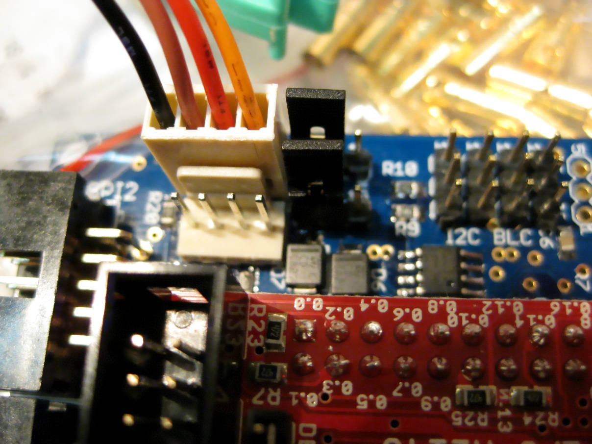
MK SerCon Cabling
If you decide to use the Mikrokopter SerCon (see further down for other options), you need a cable as follows:
UART 1 (orange) -> SerCon 7
UART 2 (red)    -> SerCon 1
UART 3 (brown)  -> SerCon 9
UART 4 (black)  -> SerCon 2
(With the LPV connecter mounted with the pins to the inside)
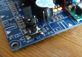
The jumper JP1 of the SerCon needs to be open and the cable needs to be connected to SIO. The SerCon needs to be powered with 5V using the 3-way jumper above the UART connector (tty0) of the FC. JP-ISP of the FC needs to be set to 2-3 for HW 0.21 to select TTY mode.
If you use a Prolific USB to serial adapter on OS X, you may need to download and install a driver, such as md_pl2303H_HX_X_dmg_v1.2.1r2.zip from http://www.prolific.com.tw/eng/downloads.asp?ID=31.
Install (flash) the NGOS firmwares
Before any of the boards can be used, they need to get our NG firmware running. Transferring the firmware to the CPUs on these boards is called flashing.
Please read the Flashing page for more information on this procedure.
Connecting to the NG
Once our firmware has been installed, you can use a Terminal program to talk to the command line shell running on the NGOS.
As the NGOS runs on the LPC-H2148, there are several ways to connect to its tty interfaces:
- Via the USB port on the LPC. This can even be done with the LPC not connected to the RC board, for a quick check whether NGOS was installed properly.
- Via one of the several UART serial interfaces on both the LPC and the RC board.
Connect via UART0 or UART1
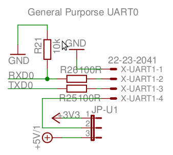
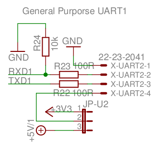
To configure and use your NG you have to connect to the NG shell waiting on UART0 or UART1. Connect a RS232 to 3.3V CMOS (e.g. SerCon) converter from your PC to the NG’s X-UART1 or X-UART2, RXD and TXD crossed. The converter can be supplied from the NG with 3.3V or 5V via Pin4, if your converter is self supplied, don’t connect Pin 4 /!\ . Pin 1 of X-UART2 is located next to R20 on the FC PCB (top view). The MK SerCon needs5V. The NGusb is powered through the usb port and for this adapter you donnot need to connect pin 4.
For the actual communication you need a RS232 Terminal application like the HyperTerminal supplied with Windows. The configuration settings for the RS232 connection are 115200 baud, 8N1 by default with flow control disabled.
You can use either the very simplistic screen command or minicom to connect.
Using Screen on the PC side as a Terminal
screen /dev/tty.usbserial 115200Of course you need to choose an appropriate device name. After connecting you need to press RETURN a couple of times. To quit screen you need to press CTRL-A CTRL-\ one after the other.
Using Minicom on the PC side as a Terminal
To prepare the connection start Minicom with the flag -s by entering minicom -s as root. Go to Serial port setup and configure the device (e.g. /dev/ttyUSB0) with 115200 Baud and 8N1. Having done that save a config file using Save setup as... As filename use minirc.usb0. You can start Minicom now with the argument usb0 to load your configuration you just made.
Repeat the above for any other device (e.g. /dev/ttyUSB1) and name the resulting config file minirc.usb1.
To connect to the UART0 enter the command minicom usb0. Next you should be able to press Return serveral times to get an NG shell prompt.
Connect via USB
Note: with this kind of connection the battery voltage measuring is not working properly!
On OS X
If you connect the LPC to a Mac, it will appear under the device name /dev/cu.usbmodemDEADC0D1. It should also be visible in the System Profiler.app under USB. (Note: You may have to install a FTDI driver extension first)
Then you can either use ZTerm.app and select the serial port named “usbmodemDEADC0D1” (also set baud rate to 115200, 8 bit, no flow control), or open Terminal.app and enter the following command:
sudo cu -s 115200 --nostop -l /dev/cu.usbmodemDEADC0D1Then press the Return key and the shell should respond with a greeting.
If the LPC does not respond, disconnect and reconnect it. Sometimes, the USB port does not start properly (using a USB Hub supposedly helps).
On Linux
To prepare the connection start Minicom with the flag -s by entering minicom -s as root. Go to Serial port setup and configure the device /dev/ttyACM0 with 115200 Baud and 8N1. Having done that save a config file using Save setup as... As filename use minirc.usb. You can start Minicom now with the argument usb to load your configuration you just made.
To connect to the LPC via USB enter the command minicom usb. Next you should be able to press Return several times to get an NG shell prompt.
Using the NG Shell
When you connect to your NG using USB or one of the UARTS you will see something similar to the following when you press Return the first time:
Wolferl-NG, Version 0.42 pre-beta (non-public), Revision r2104
Copyright (C) 2007, 2008 by the UAVP Project, http://uavp.ch,
Creative Commons Attribution-Noncommercial-Share Alike 2.5 Switzerland License
See: http://creativecommons.org/licenses/by-nc-sa/2.5/ch

Type 'show authors' for copyright owners
Type 'help' for a list of commands

#
The version and revision in the first line probably will differ. This is the status prompt of one of the NG shells running currently as NGOS Task on the NG.
If you type ps you see these tasks running:
# ps

  PID TTY         STATE    DESC
    0 /dev/usb    running  Terminal Task
    1 /dev/uart0  ready    Terminal Task
    2 /dev/uart1  ready    Terminal Task
As you can see, we are currently connected by USB since that task is in state ‘running’ while it executes the ‘ps’ command we requested.
The command help will show you all the possible shell commands.
Checking the Device Table for detected devices
Next we will check the device table. Like an Operating System the NG firmware checks all attached devices when starting up and marks detected devices in a Device Table. This device table is used by the NGOS to activate and deactivate parts of itself (which you could call Drivers). In essence the device table will show you all working devices on your NG.
To check the device table enter the command show devices:
# show devices

Detected devices:

  Addr  Bus     Description

  0x16  I2C0    Atmel 644P RC/Comm Controller
  0x18  I2C0    Atmel 328P SB Controller
  0x52  I2C1    BL-Ctrl Style (Motor 1)
  0x54  I2C1    BL-Ctrl Style (Motor 2)
  0x56  I2C1    BL-Ctrl Style (Motor 3)
  0x58  I2C1    BL-Ctrl Style (Motor 4)
  0x02  ADC12   ADXR/MLX MEMS Gyroscope 12bit (nick)
  0x01  ADC12   ADXR/MLX MEMS Gyroscope 12bit (roll)
  0x00  ADC12   ADXR/MLX MEMS Gyroscope 12bit (yaw)
  0x00  SPI0    LIS3LV02DQ 3-Axis Accelerometer
  0x02  SPI0    ADS1255 24bit Analog Digital Converter
  0x03  SPI0    AD7924 12bit Analog Digital Converter
  0x01  SBCTRL  MicroMag 3 Magnetic Compass (uncalibrated)
  0x02  SBCTRL  NMEA Global Positioning System
  0x01  RCCTRL  ACT DSL Receiver DSL0
  0x02  RCCTRL  ACT DSL Receiver DSL1
This list may differ from what your NG detects!
As you can see I currently have 4 bl-controllers (modded TowerPro25A) attached. Furthermore the system detected 3 MLX MEMS gyros, an LISL 3-axis acc, two ACT DSL receivers on UART0 and UART1.
If something is not showing up but you are sure that component is attached and should be working, then you detected a problem. You should poweroff your NG and start investingating the reasons behind the device not showing up… Are all electrical contacts fine? Does it receive power? Try to investigate from the device towards the CPU it is attached to.
If all attached devices show up correctly you can start checking the configuration.
Switching to the Default Configuration
At first you need to load a sensible default configuration. You can do that by typing set defaults:
# set defaults

All parameters reset to default values!
Switched to controller 'none'.
If your NG is beeping continuously, use the following console command to invert the signal: set HW.use.sound invert
If the beeper doesn’t beep at all, please double check if you have a jumper on JP1 on the FC. Without the jumper the beeper will not work.
This command has reset the current in-memory configuration to a set of sensible default values. It also loaded the behavior table of the configuration with the default behavior we developers defined.
There are special default settings stored in NGOS depending on propellers and sensors.
You can use set defaults [adxr10"|adxr12"|mlx10"|mlx12"] to choose specific default settings for ADXR300 or MLX sensors each with 10" or 12" propellers:
# set defaults mlx12"

All parameters reset to default values!
Switched to controller 'amir'.
Configured PID parameters and gyro type for mlx12"
Choosing a closed-loop Controller
Next you need to chose and set a closed-loop controller. With the command list ctrl you can list the available controllers:
# list ctrl

Possible 'controller' settings:

    none        The do-nothing controller (proven)
    wolferl     The Wolferl PID controller (proven)
    bearing     Bearing-Hold controller (using 3 axis 1D Kalman) (proven)
    amir        Amir's Kalman controller (3 axis 1D Kalman and more) (proven)
    amir-ng     Amir's Direction Cosine Matrix (DCM) controller (proven)
    rc-test     A 'Just forward the throttle' controller (proven)
We advise to use the amir-ng controller for first time operators. To chose the closed-loop controller type set controller amir-ng:
# set controller amir-ng

Activated controller 'amir-ng'
Setting string 'controller' to 'amir-ng'
It is also possible to use the older amir controller which is almost identical to the amir-ng-controller in terms of configuration. The amir controller is using a different algorithm though:
# set controller amir

Activated controller 'amir'
Setting string 'controller' to 'amir'
Having done this, you are ready now to inspect the global and controller configurations.
Checking the Global Configuration
Let’s look at the Global Configuration by typing show globals:
# show globals

Current global configuration:

  Name                    UAVP                Configuration name

  RC.ch.throttle          0                   RC channel throttle
  RC.ch.nick              2                   RC channel nick
  RC.ch.roll              1                   RC channel roll
  RC.ch.yaw               3                   RC channel yaw
  RC.ch.pot0              8                   RC channel pot0
  RC.ch.pot1              4                   RC channel pot1
  RC.ch.pot2              6                   RC channel pot2
  RC.ch.pot3              5                   RC channel pot3
  RC.ch.pot4              7                   RC channel pot4
  RC.ch.pot5              9                   RC channel pot5
  RC.ch.pot6              10                  RC channel pot6
  RC.ch.pot7              11                  RC channel pot7

  BAT.minimum             9.80000019          Battery minimum voltage

  TERM.mode               normal              Terminal mode

  HW.uart0.baud           115200              HW baud rate for UART0
  HW.uart1.baud           115200              HW baud rate for UART1

  HW.gyro.type            MLX                 HW gyro type

  HW.acc.horizontal       yes                 HW acc mount orientation

  HW.use.sound            normal              HW do use sound device
  HW.use.dtc              yes                 HW do use dynamic throttle control
  HW.use.acc              yes                 HW do use accelerometer
  HW.use.ngpp             yes                 HW do use NG peripherial protocol
  HW.use.compass          no                  HW do use compass
  HW.use.PT1.comp         no                  HW do use PT1 compensation

  HW.PT1.comp.k1          800                 HW PT1 parameter K1
  HW.PT1.comp.t1.down     148                 HW PT1 parameter T1 down
  HW.PT1.comp.t1.up       148                 HW PT1 parameter T1 up

  RC.death.zone           1                   RC death zone size
  RC.show.drops           no                  RC show frame drops

  RC.dev.primary          dsl0                RC primary input device
  RC.dev.secondary        dsl1                RC secondary input device

  RC.dev.mix              primary             RC device mixing type
Make sure the BAT.minimum value matches your kind of battery:
- For LiPo, a minimum of 3.3V per cell is a good value. The default of 9.8V is for a 3-cell LiPo. If your LiPo battery has 4 cells, make sure to raise this value to 13V or you’ll quickly damage your batteries by depleting them without warning if you keep them connected for too long. Once the battery reaches the minimum value, the behavior while.battery.low() will trigger, which plays 3 short beeps repeatedly by default.
Be sure to set a name for your configuration using the command set name MyNG:
# set name MyNG

Setting string 'name' to 'MyNG'
Next verify that the Gyro Type is chosen correctly!
HW.gyro.type ADXR300 HW gyro typeYou can set it using the command set HW.gyro.type [adxr300|adxr610|mlx]:
# set HW.gyro.type adxr300

Set gyro type to '5000'
Setting 'HW.gyro.type' to gyro type '5000'
Choosing the right HAL
You can configure your NG for different hardware configurations. You do this by choosing the right HAL (Hardware Abstraction Layer) for your propeller/motor configuration.
The command list hal shows all existing HALs and their current status:
# list hal

Possible 'HW.HAL' settings:

    00  none    The do-nothing HAL (proven)
    01  blc     The BLC test HAL (only for testing purposes)
    02  quad    The 4 rotor Quadcopter HAL (proven)
    03  quadX   The 4 rotor Quadcopter HAL (X-formation) (proven)
    04  quadR   The 4 rotor Quadcopter HAL (reverse) (proven)
    05  Y6      The 6 rotor Y6 Hexakopter Coax HAL (proven)
    06  X8      The 8 rotor X8 Oktocopter Coax HAL (ready for test flights)
    07  X8X     The 8 rotor X8 Oktokopter Coax HAL (X-formation) (ready for test flights)
When you have decided which HAL to use, you can choose it by setting the global variable HW.HAL:
# set HW.HAL quad

Activated propeller HAL 'quad'
Setting 'HW.HAL' to HAL 'quad'
With the commands show hal and scan actors you can verify that everything works as expected:
# show hal

Current HAL: quadcopter

    HAL Id:                    2
    HAL Description:           The 4 rotor Quadcopter HAL
    HAL Quality:               proven

    Needed number of actors:   4
    Active number of actors:   4
    Detected number of actors: 4

    Motor 1: front
    Motor 2: back
    Motor 3: right
    Motor 4: left

Description:

This is the classical 4 rotor (non-cross) QuadCopter HAL. It allows
to fly a classical QuadCopter with a front, back, left and right motor.

Current HAL configuration:

  HW.HAL     quadcopter          HW abstraction layer

# scan actors

Scanning I2C1 actor bus...
Scan finished.

Busscan results I2C1 [0x10..0xf6]
---------------------------------
Found device at 0x52
Found device at 0x54
Found device at 0x56
Found device at 0x58

Using actor addresses: 0x52, 0x54, 0x56, 0x58
Actor state machine will be STARTED in Holger BL-Ctrl mode!

Found actors in current setup: 4
Needed actors in current HAL:  4
Configuring your remote control
Now you have to configure your remote control receiver, or you won’t be able to control your NG.
ACT DSL
If you have two dsl receivers attached, you have to configure the uarts for the correct baudrate, the primary and secondary RC device and the mix device, which controls the data that is eventually used for remotecontrol-input to the NG.
  HW.uart0.baud           38400               HW baud rate for UART0
  HW.uart1.baud           38400               HW baud rate for UART1

  RC.dev.primary          dsl0                RC primary input device
  RC.dev.secondary        dsl1                RC secondary input device

  RC.dev.mix              primary             RC device mixing type
# set RC.dev.primary dsl0
Setting device in 'RC.dev.primary' to '4'
# set RC.dev.secondary dsl1
Setting device in 'RC.dev.secondary' to '5'
# set RC.dev.mix primary
Setting RC mix mode in 'RC.dev.mix' to '0'For more details, see DSL.
Sum Signal
If you don’t have an ACT DSL receiver, you will need a receiver with sum-signal output. This applies to just about every 2.4GHz System (with the exception of ACT S3D).
  HW.uart0.baud           38400               HW baud rate for UART0
  HW.uart1.baud           38400               HW baud rate for UART1

  RC.dev.primary          rcsum               RC primary input device
  RC.dev.secondary        dsl1                RC secondary input device

  RC.dev.mix              primary             RC device mixing type
# set RC.dev.primary rcsum
Setting device in 'RC.dev.primary' to '1'
# set RC.dev.secondary dsl1
Setting device in 'RC.dev.secondary' to '5'
# set RC.dev.mix primary
Setting RC mix mode in 'RC.dev.mix' to '0'All remotes
Be sure to verify the RC.ch.* variables. They define what RC channel gets mapped onto what function. Depending on your type of rc receiver you can check our RC channels with the command print rcsum when using an rc-sum receiver or with the command print dsl channels when using a ACT DSL receiver as I do:
# print dsl channels

DSL Parser on uart0:

    Signal quality:     0
    Battery:            0
    Channel:            0

    -C00- -C01- -C02- -C03- -C04- -C05- -C06- -C07- -C08- -C09- -C10- -C11-
     N/A   N/A   N/A   N/A   N/A   N/A   N/A   N/A   N/A   N/A   N/A   N/A

DSL Parser on uart1:

    Signal quality:     0
    Battery:            0
    Channel:            0

    -C00- -C01- -C02- -C03- -C04- -C05- -C06- -C07- -C08- -C09- -C10- -C11-
     N/A   N/A   N/A   N/A   N/A   N/A   N/A   N/A   N/A   N/A   N/A   N/A

DSL Parser on dsl0:

    Signal quality:     123

    -C00- -C01- -C02- -C03- -C04- -C05- -C06- -C07- -C08- -C09- -C10- -C11-
    +006  +000  +000  +001  +123  -118  +000  +000  +000  +000  +000  +000

DSL Parser on dsl1:

    Signal quality:     117

    -C00- -C01- -C02- -C03- -C04- -C05- -C06- -C07- -C08- -C09- -C10- -C11-
    +006  +000  +000  +001  +123  -118  +000  +000  +000  +000  +000  +000
In the above case I had two DSL receivers attached.
You could also use the commands loop dsl rcsum, loop dsl rcsumS3D, loop dsl uart0, loop dsl uart1, loop dsl dsl0, loop dsl dsl1 or loop dsl rccsum
# loop dsl dsl0

DSL on dsl0

Press any key to stop...

-C00- -C01- -C02- -C03- -C04- -C05- -C06- -C07- -C08- -C09- -C10- -C11-
+006  +000  +000  +001  +123  -118  +000  +000  +000  +000  +000  +000
When you have identified the right channel numbers set them in the global configuration using the command set <variable> <value>:
# set RC.ch.nick 2

Setting integer 'RC.ch.nick' to '2'
Repeat the above until all RC.ch.* variables are setup correctly. Be carefull: controller channels are not the same as the RC.ch numbers. Your controller channel is 1,2,3,4 and in NGOS the channels are numbered 0,1,2,3. So if your pitch channel is on you controller on channel 1, you should:
# set RC.ch.nick 0

Setting integer 'RC.ch.nick' to '0'
The following picture shows the sticks of a transmitter from above in mode 2,
be sure to have C00 raising when pushing the left stick to the top, C02 raising when pushing the right stick to the top etc.
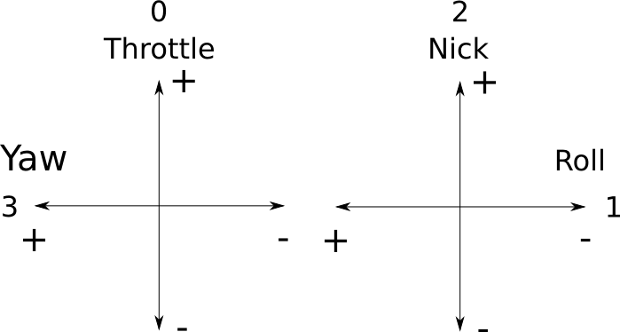
If any channel has a different orientation, you have to invert it on your remote-control.
Checking Controller Configuration
Next you can check the closed-loop controller dependent variables. These variables change in number and name, when you switch between different closed-loop controllers. They are bound to the controller.
You see the controller dependent variables when entering the command conf show:
# show conf

Current system configuration:

  Controller            amir                Closed-loop controller

  T.idle                20                  Throttle idle speed
  T.reserve             20                  Throttle control reserve
  T.spinup              2                   Throttle spinup time (sec)

  P.nick                95                  Nick proportional factor
  P.roll                95                  Roll proportional factor
  P.yaw                 95                  Yaw proportional factor

  D.nick                500                 Nick differential factor
  D.roll                500                 Roll differential factor
  D.yaw                 100                 Yaw differential factor

  I.nick                45                  Nick integral factor
  I.roll                45                  Roll integral factor
  I.yaw                 17                  Yaw integral factor

  Kalman.Angle.Q        0.00030000          Kalman angle process var
  Kalman.Bias.Q         0.00010000          Kalman bias process var
  Kalman.Acc.R          3.00000000          Kalman system var
  Kalman.Cycle          1                   Kalman update intervall
  Kalman.Limit          1                   Kalman gyro stationary limit

  P.z                   1950                Height proportional factor
  D.z                   5000                Height differential factor
  I.z                   0                   Height integral factor

  P.z.limit             20                  Height correction limiter
  P.z.upfact            28                  Upwards height correction (%)

  KalmanZ.L1            1.29170001          Height Kalman-Bucy L1 factor
  KalmanZ.L2            0.83420002          Height Kalman-Bucy L2 factor
  KalmanZ.L3            -0.26930001         Height Kalman-Bucy L3 factor

  RC.nickcorr           0                   RC nick correction
  RC.rollcorr           0                   RC roll correction
  RC.yawcorr            0                   RC yaw correction
  RC.throttlehoover     -1600               RC hoover throttle

  ACC.nickcorr          0                   Nick Acc correction
  ACC.rollcorr          0                   Roll Acc correction
  ACC.yawcorr           0                   Yaw Acc correction

  TRIM.roll             0                   Direct motor roll correction
  TRIM.nick             0                   Direct motor nick correction
  TRIM.yaw              0                   Direct motor yaw correction

  RC.fact.nick          30                  RC stick factor nick
  RC.fact.roll          30                  RC stick factor roll
  RC.fact.yaw           65                  RC stick factor yaw

  Axis.decoupling       yes                 Axis decoupling
The above output looks different for every closed-loop controller!
As you can see you can configure all closed-loop controller variables. You can change them with the same set <variable> <value> command as Global Variables.
Calibrating your sensors
Calibrating your gyros
Next, we make sure that the NG is correctly aware of its sensor data. For that we have to calibrate gyro sensors.
The calibration of the gyros does not require a flat surface, but it is necessary that the NG does not move during calibration.
One way to calibrate your sensors is to use your RC. Move the trottle stick to the upper left corner. This will calibrate your gyros. Your NG will signal the calibration with 3 short beeps. To store it move the stick to the mid-right position. The NG will beep again.
If you want to calibrate the sensors using the console simply type in calibrate gyro and you’re done.
Calibrating your accelerometer (NGOS < v0.68)
Before calibrating the accelerometer the NG must be placed on a flat horizontal surface. This is important because the input from the acceleration sensor during calibration is used to determine the NG´s horizontal orientation during flight.
Next, after putting your NG on a flat table, make sure it is perfectly horizontal and then move your throttle stick to the upper, right corner. This will calibrate your accelerometer. Your NG will signal that with 3 longer beeps. To store it move the stick to the mid-right position. The NG will beep again.
If you want to calibrate the sensors using the console simply type in calibrate acc and you’re done. Make sure the NG is perfectly horizontal while calibrating the accelerometer.
Calibrating your accelerometer (NGOS >= v0.68)
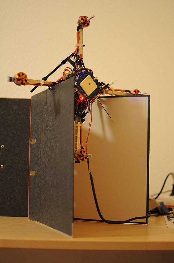
Since NGOS version 0.68 calibrating the accelerometer is somewhat different. As before you simply type calibrate acc.
The following will be shown:
ACC measurement 1: 0 degrees turned *press return to measure or q to quit*Be sure to put your NG on a flat horizontal surface and hit return. You will see something like this (don’t care about the values. My surface for testing this was not perfectly flat at all):
ACC Measurements: ..............................

ACC measurement 0 (0 degrees turned) for axis 0: -8 (-11 - -6)
ACC measurement 0 (0 degrees turned) for axis 1: 20 (17 - 23)
ACC measurement 0 (0 degrees turned) for axis 2: -1014 (-1021 - -1011)

ACC measurement 1: 90 degrees turned  *press return to measure or q to quit*
You now need to turn your NG 90 degrees. Just start with the nick axis. That means the nose of your NG and with that also the white arrow on your FC has to point to the ground. Hit return again:
ACC Measurements: ..............................

ACC measurement 1 (90 degrees turned) for axis 0: 5 (2 - 14)
ACC measurement 1 (90 degrees turned) for axis 1: 1023 (1022 - 1024)
ACC measurement 1 (90 degrees turned) for axis 2: 89 (82 - 100)

ACC measurement 1: 180 degrees turned  *press return to measure or q to quit*
Now put your NG upside down (180 degrees) and press return again:
ACC Measurements: ..............................

ACC measurement 2 (180 degrees turned) for axis 0: -11 (-12 - -10)
ACC measurement 2 (180 degrees turned) for axis 1: -22 (-26 - -21)
ACC measurement 2 (180 degrees turned) for axis 2: 1026 (1025 - 1029)

ACC measurement 1: 270 degrees turned  *press return to measure or q to quit*
Continue rolling your NG around the nick axis so that the tail of your NG now points down to the ground. The white arrow on your FC now points up. After the next return you should get something like:
CC Measurements: ..............................

ACC measurement 3 (270 degrees turned) for axis 0: -61 (-68 - -57)
ACC measurement 3 (270 degrees turned) for axis 1: -1016 (-1017 - -1014)
ACC measurement 3 (270 degrees turned) for axis 2: -24 (-32 - -18)

Calculating ACC calibration:
ACC calibration for axis 0: a*g = +0033, b = -18  -> not accepted
ACC calibration for axis 1: a*g = +1019, b = +1  -> accepted
ACC calibration for axis 2: a*g = +1021, b = +19  -> accepted

Attention: Not yet all axis calibrated, restarting calibration cycle...

ACC measurement 1: 0 degrees turned  *press return to measure or q to quit*
As you can see two axes have been accepted. Now you have to do the same for the roll axis. First place your NG steady on the flat surface again an hit return:
ACC Measurements: ..............................

ACC measurement 0 (0 degrees turned) for axis 0: -15 (-17 - -13)

ACC measurement 1: 90 degrees turned  *press return to measure or q to quit*
Now let the starboard side (the right side) of your NG point down to the ground. Again return:
ACC Measurements: ..............................

ACC measurement 1 (90 degrees turned) for axis 0: 1013 (1013 - 1015)

ACC measurement 1: 180 degrees turned  *press return to measure or q to quit*
Put your NG upside down again and press enter:
ACC Measurements: ..............................

ACC measurement 2 (180 degrees turned) for axis 0: -1 (-3 - 2)

ACC measurement 1: 270 degrees turned  *press return to measure or q to quit*
And as last step let the larboard side (the left side) of your NG point down and hit return:
Calculating ACC calibration:

ACC calibration for axis 0: a*g = +1015, b = -5  -> accepted
ACC calibration for axis 1: a*g = +1019, b = +1  -> accepted
ACC calibration for axis 2: a*g = +1021, b = +19  -> accepted

Calibrated ACC values:

Press any key to stop...

Raw: -1017 +0009 +0051  Calibrated: -0997, +0007, +0031
As you can see ACC calibration was calculated and all three axes have been accepted. After this NGOS shows the raw and calibrated values in a loop. Each side of your NG pointing down to the ground should result in a value of 1000 or -1000 for one of the three values.
Hit any key will show…
Storing new calibration to global registers…and you’re done.
Calibrating valid measurements for your accelerometer
As an accelerometer not only measures gravity - which is what we need to measure to know what horizontal means - but also external accelerations, we need to validate the measurements done by our accelerometer. As long, as no external acceleration force exists, the accelerometer measures gravity and the vector of gravity always points towards the earth. It’s length is 9.81m/s^2 as long as no external acceleration force exists.
By calculating the length of the measured acceleration vector and comparing it to 9.81m/s^2 we are able to qualify our measurement. A configuration variable of your NGOS defines how much divergence of that value we accept when using the measurement.
To find the right ACC.valid value, you should start by setting it to -250 with the command set ACC.valid -250. The minus sign activates a special routine which will beep, whenever your NG accepts a measurement. This will help you find the right value for ACC.valid.
Next you lower the value of ACC.valid from -250 to -240 to -230 and so on, until your NG will sometimes beep when standing still on solid ground. This is the barrier value. At this value your NG will drop sometimes - but seldom - a measurement because it’s acceleration vector length exceeds the value defined by ACC.valid.
After you completed your first flights you can do the following to make sure the ACC.valud value is ok:
Start your motors and hoover in front of you. Your NG should often drop a acceleration measurement, but not too often so that it still gets a correct measurement now and then, when no external acceleration forces are in place. Next fly a 3 axis curve and observe that your NG beeping the whole time while doing the curve and while external acceleration forces exist. As soon as your NG starts to stand still and no external acceleration happens, you should hear sometimes no beeps, as it again will use the best measurements when they do not diverge too much.
Having done the above, make sure to set the found ACC.valid to it’s positive value to disable to beeping feature. Eg. if your found value for ACC.valid is -170 set it to 170 with set ACC.valid 170.
Calibrating your compass
Calibration of the compass has to be done on the terminal of the sensor board.
# calibrate compass

Calibrating compass:

Move your NG or press any key to end calibration!

x[0000..0000], y[0129..0132], z[0000..0000]
Note: Depending on the compass you’re using, you have to type “calibrate compass”, “calibrate mk3mag” or “calibrate hmc5883l”. Available commands for calibration can always be seen on the shell by typing “help calibrate”.
When calibration is started, you have to move your NG 360° on all 3 axis. This way the compass can find the highest and lowest value the compass delivers. Press a key to stop, and you should see the MicroMag3 in the device list after next reboot. The led should start to blink which tells you that calibration is done and in use.
Storing the Configuration
After having configured everything type the command conf store:
# conf store

Storing current configuration to slot 0 in flash memory sector 26... succeded!
This will store your global and controller configuration to the configuration slot 0 which is the Default Configuration Slot. You can check out your configuration slots by entering the command conf list:
# list conf

Currently occupied configuration slots:

  Default       Integral-Flight-38

  Slot 1        Integral-Flight-38
  Slot 2        HH-Flight-38
  Slot 3        Wolferl-Flight-38
  Slot 4        Integral-Flight-50
As you can see you have several coniguration slots you can use. The command to store to a specific slot is conf store <x> and conf load <x>. The Default Configuration is the one which gets automatically loaded when powered up and also the one which gets used by the commands conf store and conf load without numerical argument.
There’s also a behavior rule allowing you to store your configuration using your RC. Move your throttle stick to the middle, right position. This will call conf store and store your configuration to the default slot.
After storing your configuration to the Default Configuration Slot you are ready for a test spinup.
The LED and Beeper Signals are listed on the Signals Page.
Now work through the Pre Flight Checklist to make sure everything works correctly.