30A
| Documentation / HOWTO / BL-Ctrl/HK-BlueSeries | /30A | /12A |
HobbyKing 30A Blue Series (N-Fets only) Modification for I2C
/!\ There are no guarantees for the correctness of the following stuff. Please be careful and work carefully when doing the modifications on your controllers. Test your modifications with the current limit set to max. 1 Ampere.
Requirements
I used these elements to do the conversion. You can reprogram the Atmel with other programmers as well…
- Schematic with detailed modification description which you can find here
- Thin (diameter ~0.12mm) enameled copper wire
- 80W solder iron with thin solder tip and thin solder
- HotAir gun
- AVR ISP mkII and AVR-dude on a linux machine and hex-files from below
- Labroratory PSU, Motor and a NG-UAVP to verify if they are working
- A lot of HK30A BlueSeries BLDC-controllers ;)
Preliminary work
- Preheat your solder iron ;)
- Desolder the signaling cable.
Modify your controller step by step description
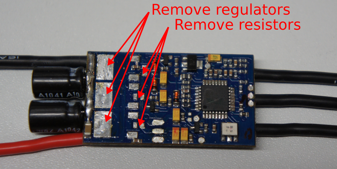 | Remove the unneeded parts of the BEC. The small resistors should be no problem to remove. The voltage converter (the big black parts) are somewhat cumbersome, they absorb a lot of heat (Use a soldering iron with more then 60 watts or preheat the PCB with HotAir to about 150deg Celsius). I also added some PB-solder, which lowered the melting point of the Pb free solder used by factory and lowers the thermal resistance too. |
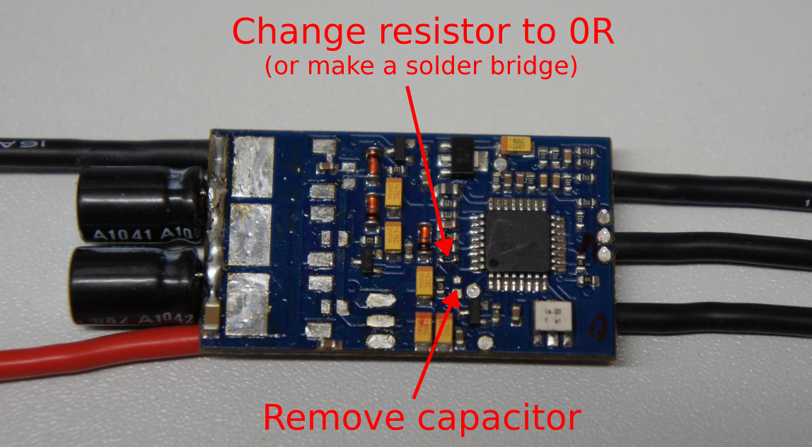 | Remove the capacitor from the RC low pass filter of the old PPM-signal input and replace the resistor by a 0R jumper resistor or a solder bump. |
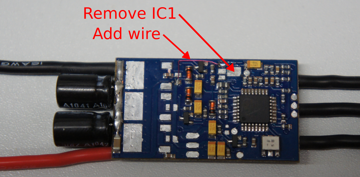 | /!\ Perform this step only, if you want to power your BLDC MCU directly from your NG, otherwise immediately proceed with the next step. /!\ |
| Remove the small voltage regulator IC1 and add a wire as shown in the picture. |
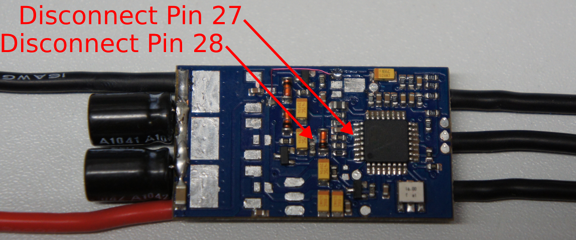 | Two conducting paths have to be disconnected at this step. The first one will be directly in front of pin 27 from the MCU (directly left of the MCU in the picture shown to the left). This one can be disconnected with a fine cutter like a scalpel. The second one is the via to the inner layer at the resistor between the tantal capacitor to the left and the diode at the right side shown in the picture to the left. For removing the connection you can use a small drill with a diameter of 0.6mm. At last measure the old connection, it should be high impedance. |
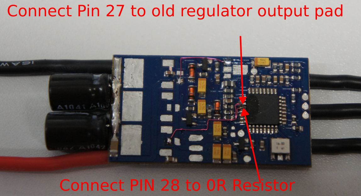 | Connect Pin 28 with a enameled copper wire to the previously replaced resistor or solder bump from step 2. Thats your new SCLK connection of the I2C interface from NG to the MCU. Now connect Pin 27 to the unused copper wire with their pads on the PCB as shown in the picture to the left. The pad above is now the SDA Pin of the I2C interface. |
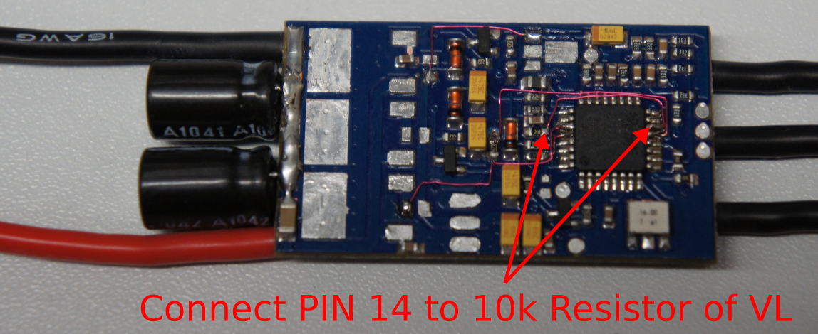 | Now the VL signal has to be connected to pin 14. The best way is to solder a enameled copper wire to pin 14 and connect the other end to the right side of the 10k pull down resistor in front of pin 27 and 28. |
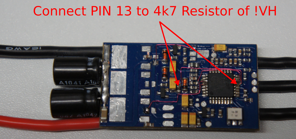 | The VH signal can be connected in the same way from Pin 13 to the upper end of the 4k7 resistor between the Tantal capacitor and the diode as shown in the picture to the left. |
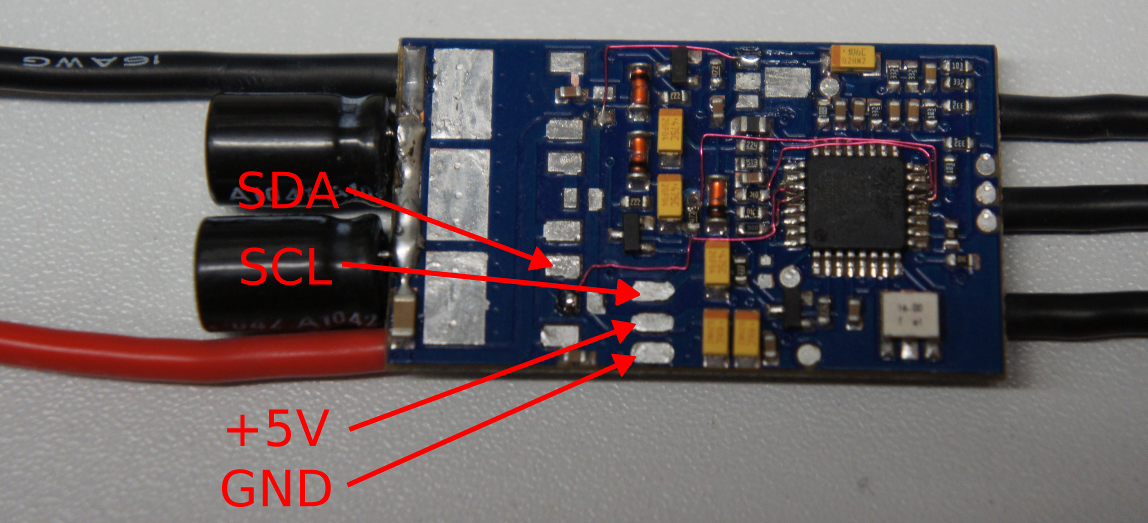 | Your BLDC is now completely modified. To the left you can see the pin out for the signaling cable to the NG. |
Load new Firmware
The software for I2C communication was written by Quax. I made some changes to support the HK-BlueSeries-30A controllers. The firmware is available as a binary as well as a hex file. You can flash the controller with AVRdude.
You can download the firmware here.
For programming there are pads on the top side of the board, shown in the picture below:
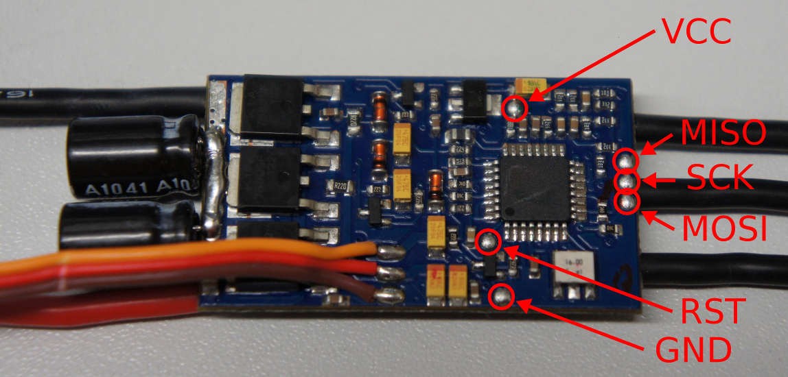
They have to be connected to the programmers interface. To flash the new firmware, follow the command line instructions below: . {{{ % avrdude -p m8 -c avrispmkII -P usb -U flash:w:hk-30a-blueseries-m1.hex
avrdude: Version 5.10, compiled on Jan 19 2010 at 18:43:51 Copyright (c) 2000-2005 Brian Dean, http://www.bdmicro.com/ Copyright (c) 2007-2009 Joerg Wunsch
avrdude: AVR device initialized and ready to accept instructions
Reading | ################################################## | 100% 0.01s
avrdude: Device signature = 0x1e9307 avrdude: safemode: lfuse reads as A4 avrdude: safemode: hfuse reads as DF avrdude: NOTE: FLASH memory has been specified, an erase cycle will be performed To disable this feature, specify the -D option. avrdude: erasing chip avrdude: reading input file “tp-25a-new-m1.hex” avrdude: input file hk-30a-blueseries-m1.hex auto detected as Intel Hex avrdude: writing flash (2132 bytes):
Writing | ################################################## | 100% 0.82s
avrdude: 2132 bytes of flash written avrdude: verifying flash memory against hk-30a-blueseries-m1.hex: avrdude: load data flash data from input file hk-30a-blueseries-m1.hex: avrdude: input hk-30a-blueseries-m1.hex auto detected as Intel Hex avrdude: input hk-30a-blueseries-m1.hex contains 2132 bytes avrdude: reading on-chip flash data:
Reading | ################################################## | 100% 0.63s
avrdude: verifying … avrdude: 2132 bytes of flash verified
avrdude: safemode: lfuse reads as A4 avrdude: safemode: hfuse reads as DF avrdude: safemode: Fuses OK
avrdude done. Thank you. }}}
After several seconds the firmware should be flashed. You are ready to start the controller.
First Start
A first test should be done by connecting a laboratory PSU to the battery wires with 12V and the current limit to 1 Ampere. Additionaly if you removed the voltage regulator IC1, you have to connect 5V to power at the signaling cable connection. On both rails there should only flow a few milliamp (<25mA).
/!\ The current limiter should not kick in while booting the firmware. /!\
If the first test succeeds, you can connect a motor to the BLDC and power up again. While booting the firmware you should her a noise like this:
- attachment:hk-tp25a-peep-v2009x.mp3
As opposed to the original sound:
- attachment:hk-tp25a-peep-original.mp3
Tests
If you have a flight control you can connect the brushless controller to that. Make sure you connect SCL to SCL and SDA to SDA on the flight control. Additionally check for right polarity of the 5V from the NG.
Type this command to detect the actor:
. {{{
scan actors
Scanning I2C1 actor bus… Scan finished.
Busscan results I2C1 [0x10..0xf6]
Found device at 0x56
Found actor addresses: Actor state machine will be STARTED in Holger BL-Ctrl mode!
Found actors in current setup: 1 Needed actors in current HAL: 0 }}}
As yo can see, my flight control found motor number three. To test it, you have to connect all actors your hal needs (four for normal four motor quadrocopter, “set HW.HAL quadcopter”). Then you can use the command enable/disable motor to start a motor:
. {{{
enable motor 1
show actors
… Actor Activation Status:
Actor 1: enabled (front)
Actor 2: disabled (back)
Actor 3: disabled (right)
Actor 4: disabled (left)
disable motor 1
}}}