NGBLC-4mini
| Construction | /HW-0.22 | /HW-0.22-mini | /HW-0.23-mini | /HW-0.24-mini | /NGBLC-4mini | Next Chapter |
NGBLC-4mini
About
Why we built our own BLC
The UAVP-NG Multicopter Project did not have its own brushless motor controller (BLC) for a long time. Since NGOS supports I2C brushless motor controllers from other projects, such as the Mikrocopter MK-BLC, 1hoch4 BLC as well as various modified Chinese BLCs using firmware from Bernd Konze (aka Quax), there was no pressing need for our own BLC design.
Everything changed when Chinese suppliers started changing their BLC designs in rapid succession, making the modifications harder and harder. So we decided to design our own BLC, with the features specifically required and desired for our project. The BLC4 design places controllers for four motors on a single PCB which helps us to conserve space and save weight, since we now use less cabling to interconnect the BLC to the FC.
Specification
- 4x separate BLCs on one PCB (55mm x 55mm PCB) Same form-factor as the NG MINI FC PCB
- Compatible with:
- Quax firmware
- SimonK firmware (only using our modified version for Atmega168)
- 30A Peak Current
- 4x 16MHz ATMEGA168A CPUs
- Compatible with 2S to 4S LiPos / LiFePos
- I2C and UART interface
- Input cable reduced to:
- 1 battery input (+/-)
- 4 Pin I2C or 6 Pin UART connector (5V,SCL,SDA,GND,RXD,TXD)
Power Supply Options
- 5V power must be supplied by the external Flight Controller board. The BLC does not need its own power supply. The Flight Controller turns the BLC on and off. Batteries are protected from discharging over long time periods because of minimal shutdown current.
- Enable 5V power supply on-board the BLC. The Flight Controller turns the BLC on and off with a 5V signal from the FC. Batteries are protected from discharging over long time periods because of minimal shutdown current.
- Enable 5V Power Supply on-board the BLC. The BLC power supply is always on. This permits the use of our BLC4 with other Flight Controllers, such as Mikrokopter or Armocopter. The BLC power supply is not switched off. You have to protect the discharging of your battery on your own.
PCB Assembling
/!\ Soldering this PCB is not easy and certainly not possible for beginners. Do not attempt this if you have no experience in soldering small SMD parts. Expect additional difficulties in getting enough heat to solder the parts on the board because of the large amount of copper inside the PCB. You need a LARGE soldering-iron-tip for soldering this board.
Order of soldering
- MOSFETs
- Oscillator
- Capacitors between Half-Bridge-Drivers
- Half-Bridge-Drivers
- ATMEGAs
- all Ceramic Capacitors, C17 is too near to IC5 and has to be soldered at the edge of the pads in the direction of IC7
- all Resistors
- all Diodes and LEDs
- Presicion Resistors
- Electrolytic Capacitors
- Molex Picoblade Connectors
- Step-Down Switching Regulator
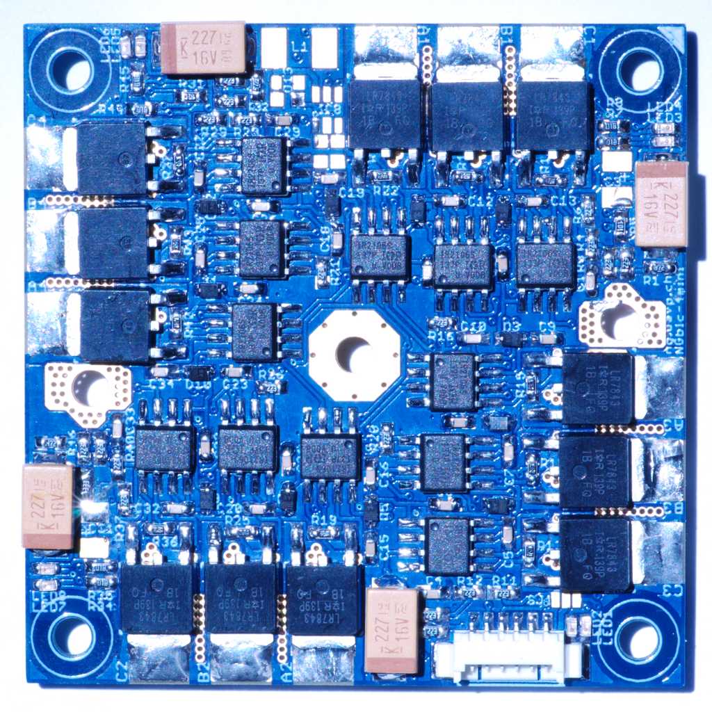
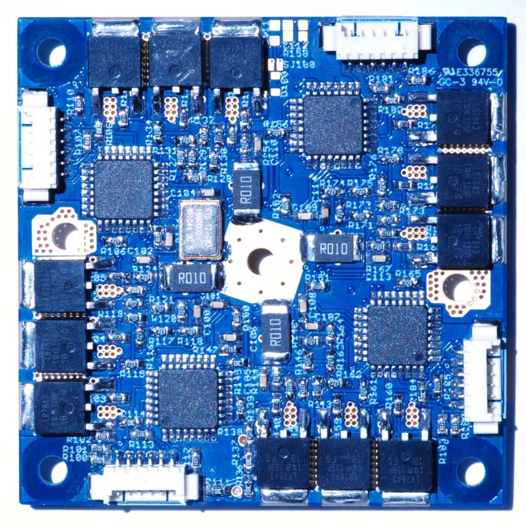
Empty Boards
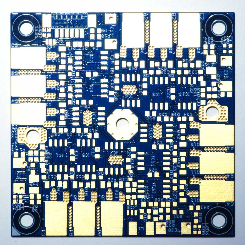 | 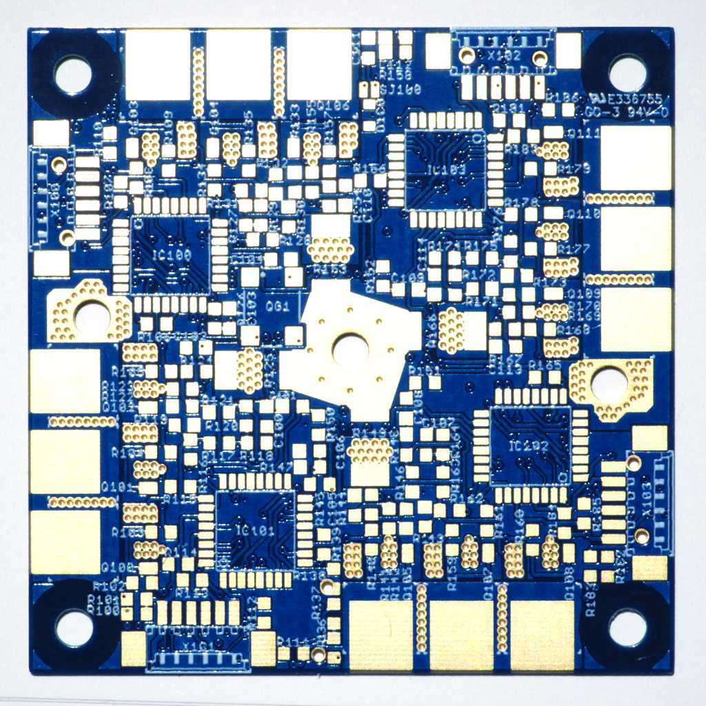 |
FETs
Start with soldering the FETs. They are not easy to solder, since both the FETs themselves and the large copper patches on the PCB below them are HUGE heatsinks. Use a wide soldering-iron-tip, and turn your iron up to 350 degree C. Do not attempt this if your sodlering iron has less than 60W.
If you don’t have any hot-air soldering station available, you can just pre-tin the large Pads below the FETs, and slide the FETs slowly on the Pads from the center of the PCB while keeping your soldering iron on the Pad an on the top edge of the heat-sink of the FET simultaneously.
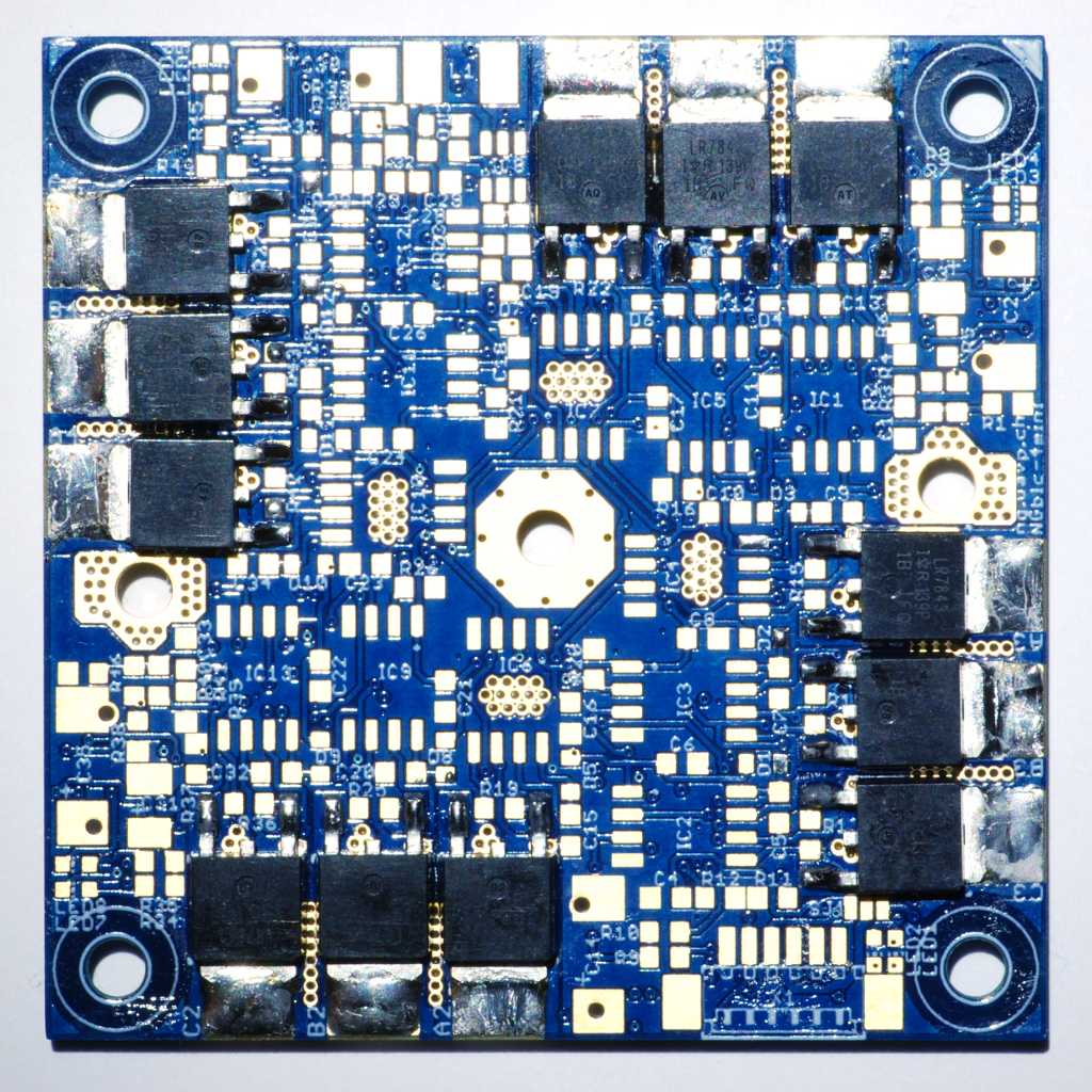 | 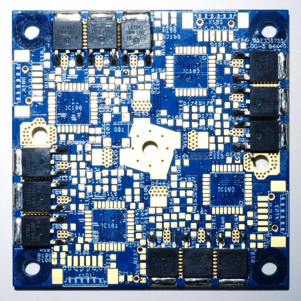 |
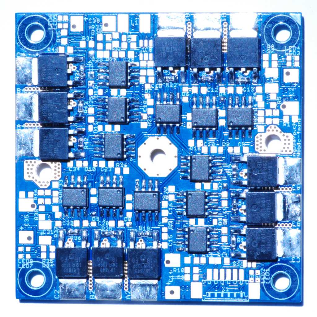
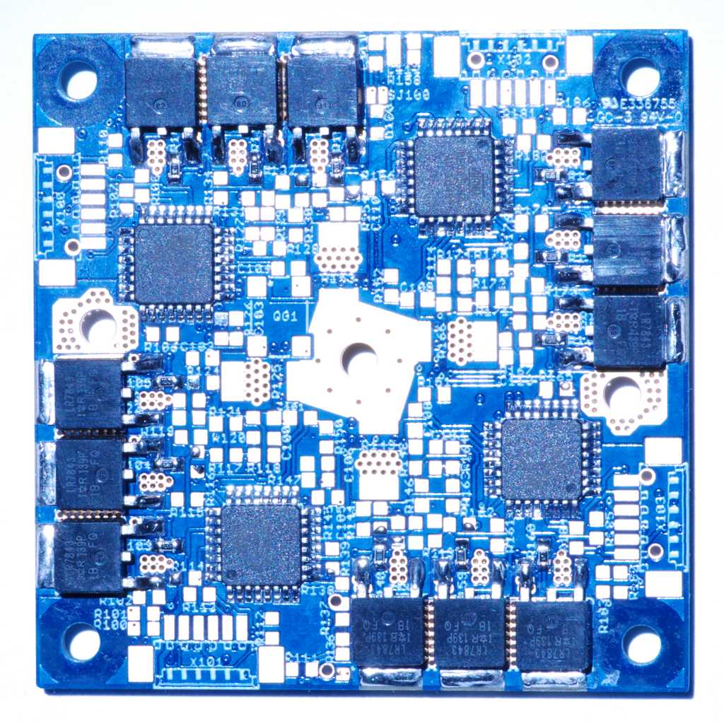
Half-Bridge-Drivers and Atmegas
Contrary to the pictures, start with soldering the Capacitors between the FET drivers. As you can see on the pictures, space between the FET-drivers is very limited. The Continue with the FET-drivers and the Atmegas.
 |  |
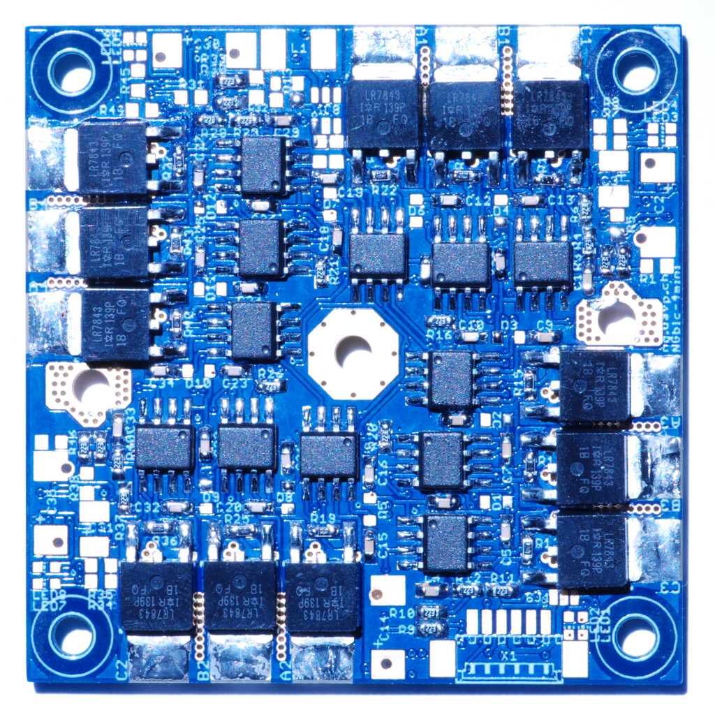
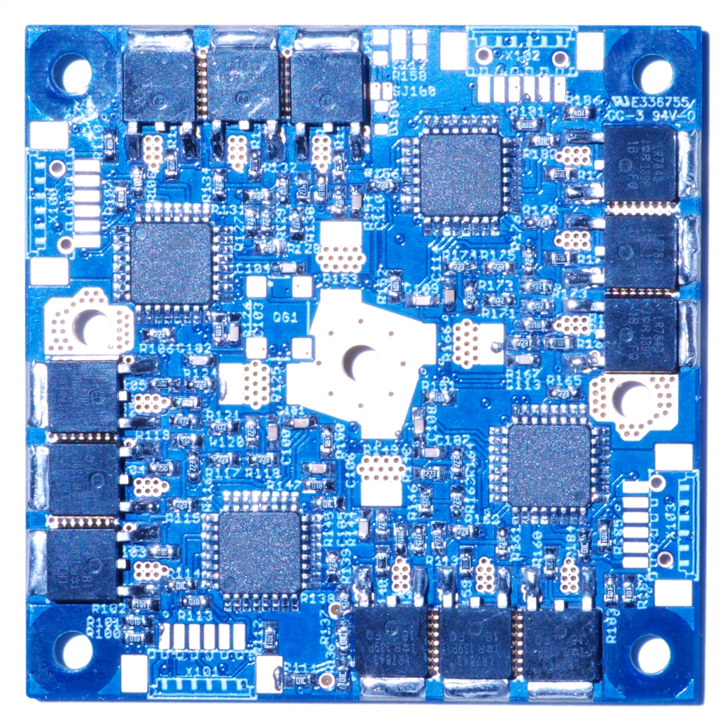
Small stuff: Resistors, Capacitors
Now continue with all the small Resistors and Capacitors. Since the Diodes have legs, they are easy to be soldered from above, so solder them after all the Resistors and Capacitors.
 |  |
Large Resistors, Capacitors, Connectors
Now solder on the remaining LEDs, large Capacitors and large Resistors. Solder the picoblade connectors after everything else is finished, since they are temperature-sensitive and block access to a few other parts.
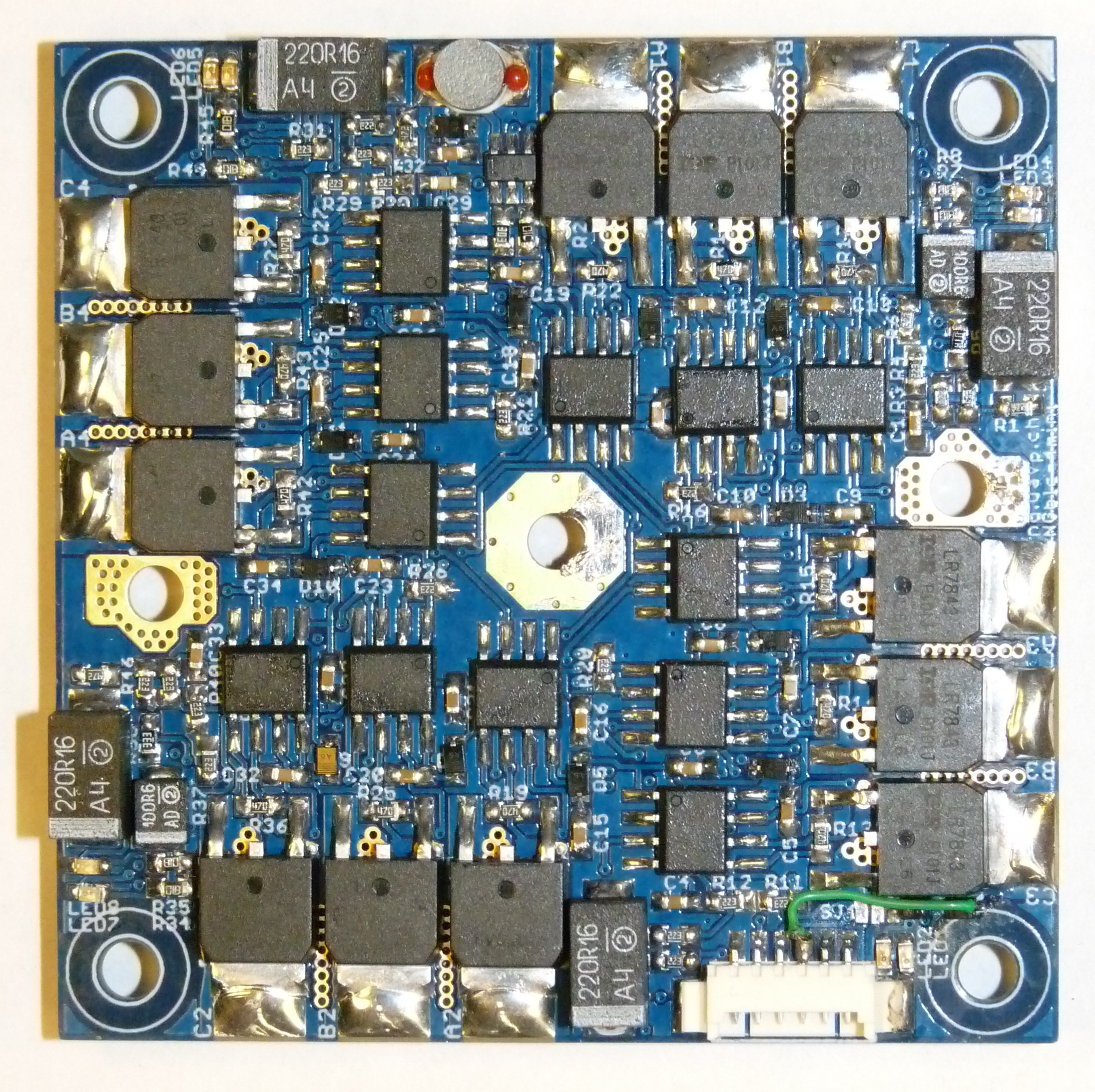
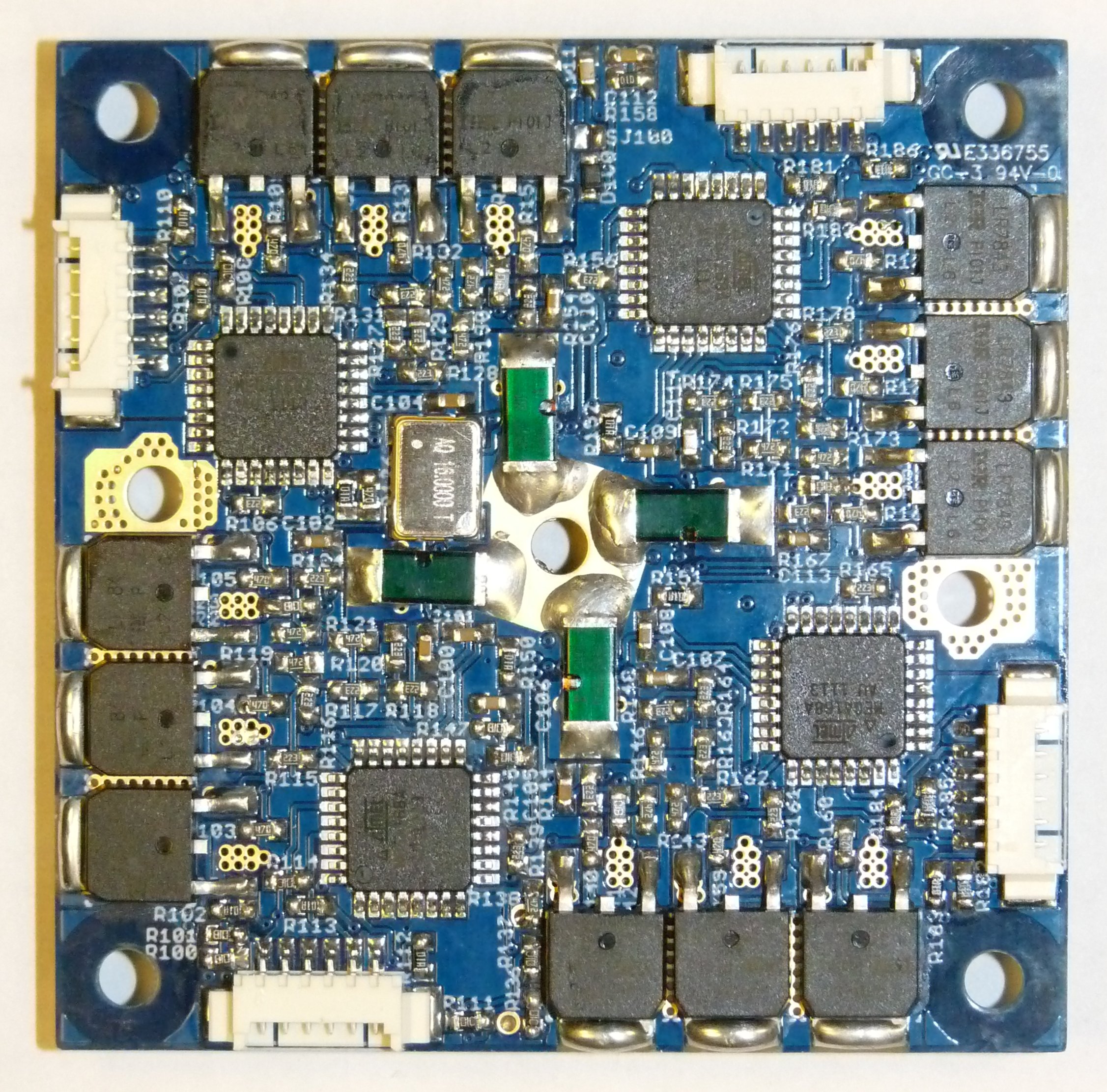
 |  |
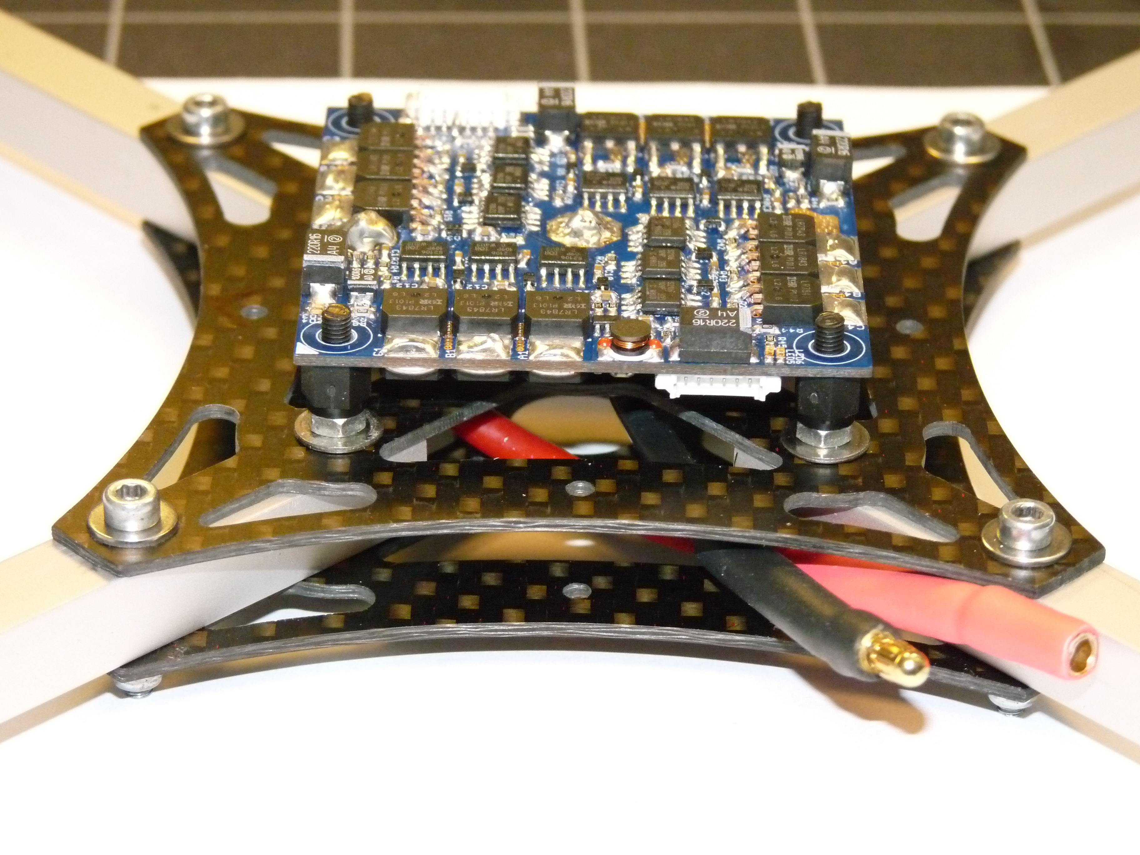
The fully assembled NGblc-4mini PCB
 |  |
Jumper
NGBLC-4mini r0
The Jumpers SJ1 and SJ100 are needed to select the 3 Power Supply options from above:
| Jumper | Description | bridge 1 2 | bridge 2 3 |
| SJ100 | powered by FC | open | |
| SJ1 | powered by FC | closed | open |
| SJ100 | self powered, switched by FC | open | |
| SJ1 | self powered, switched by FC | open | /!\ patch* |
| SJ100 | self powered, always on | closed | |
| SJ1 | self powered, always on | open | open |
** There has to be a patch with 2x 1N4148 diodes in series from pad 2 to pad 3 (or do it from connector X1 pin4 to SJ1 pad 3)*
NGBLC-4mini later than r0
The jumpers SJ100 and SJ101 are needed to select the 3 Power Supply options from above:
| Jumper | Description | bridge 1 2 | bridge 2 3 |
| SJ100 | powered by FC | open | |
| SJ101 | powered by FC | closed | open |
| SJ100 | self powered, switched by FC | open | |
| SJ101 | self powered, switched by FC | open | closed |
| SJ100 | self powered, always on | closed | |
| SJ101 | self powered, always on | open | open |
The jumpers SJ1 and SJ2 are needed to select the the way of communication interface (I2C or UART):
| Jumper | Description | bridge 1 2 | bridge 2 3 |
| SJ1/SJ2 | I2C | close | open |
| SJ1/SJ2 | UART | open | close |
Plugs
NGBLC-4mini r0
The different plugs on the PCB:
| Name | Function | Pins |
| X1 | interface (5V TTL) | 1-GND, 2-SDA, 3-SCL, 4-5V, 5-RXD, 6-TXD |
| X100 | ISP Motor 1 | 1-5V, 2-MOSI, 3-MISO, 4-SCK, 5-RESET, 6-GND |
| X101 | ISP Motor 3 | 1-5V, 2-MOSI, 3-MISO, 4-SCK, 5-RESET, 6-GND |
| X102 | ISP Motor 4 | 1-5V, 2-MOSI, 3-MISO, 4-SCK, 5-RESET, 6-GND |
| X103 | ISP Motor 2 | 1-5V, 2-MOSI, 3-MISO, 4-SCK, 5-RESET, 6-GND |
NGBLC-4mini later than r0
The different plugs on the PCB:
| Name | Function | Pins |
| X1/X7 | interface (5V TTL) | 1-GND, 2-SDA/RXD (see SJ1/SJ2), 3-SCL/TXD (see SJ1/SJ2), 4-5V |
| X100 | ISP Motor 1 | 1-5V, 2-MISO, 3-MOSI, 4-SCK, 5-RESET, 6-GND |
| X101 | ISP Motor 3 | 1-5V, 2-MISO, 3-MOSI, 4-SCK, 5-RESET, 6-GND |
| X102 | ISP Motor 4 | 1-5V, 2-MISO, 3-MOSI, 4-SCK, 5-RESET, 6-GND |
| X103 | ISP Motor 2 | 1-5V, 2-MISO, 3-MOSI, 4-SCK, 5-RESET, 6-GND |
Before you Flash the NGBLC
Connect the NGBLC to a Laboratory power supply. Power it up with 5V on X1 on Pin 4 or via FC. It should not use more than 100-200mA in that stand-by mode. Now you are ready for flashing! Note that you may cannot use the current limit function in the power supply because of hight starting current peaks.
Flashing
When you flash the ATMEGAs, check the schematics or table for the right connector (X100-X103). In order to flash the correct motor number hex file to the ATMEGA that belongs to the coresponding motor.
Quax Firmware
Programming and Fuses in Atmel Studio 4
As software for compiling and flashing i am using Atmel AVR Studio 4 (don’t use version 5, only trouble)
Download AVR Studio 4 - Registration needed
As programming device you may use Atmel AVR Dragon or USBprog. Mine is USBprog 3.0
You can also use avrdude. For example, to flash BLC1 using a cheap USBASP programmer:
sudo avrdude -p m168 -c usbasp -P usb -v -B 8 -U flash:w:ngblc-quax-M1.hex -U lfuse:w:0xe7:m -U hfuse:w:0xdf:m # for BLC1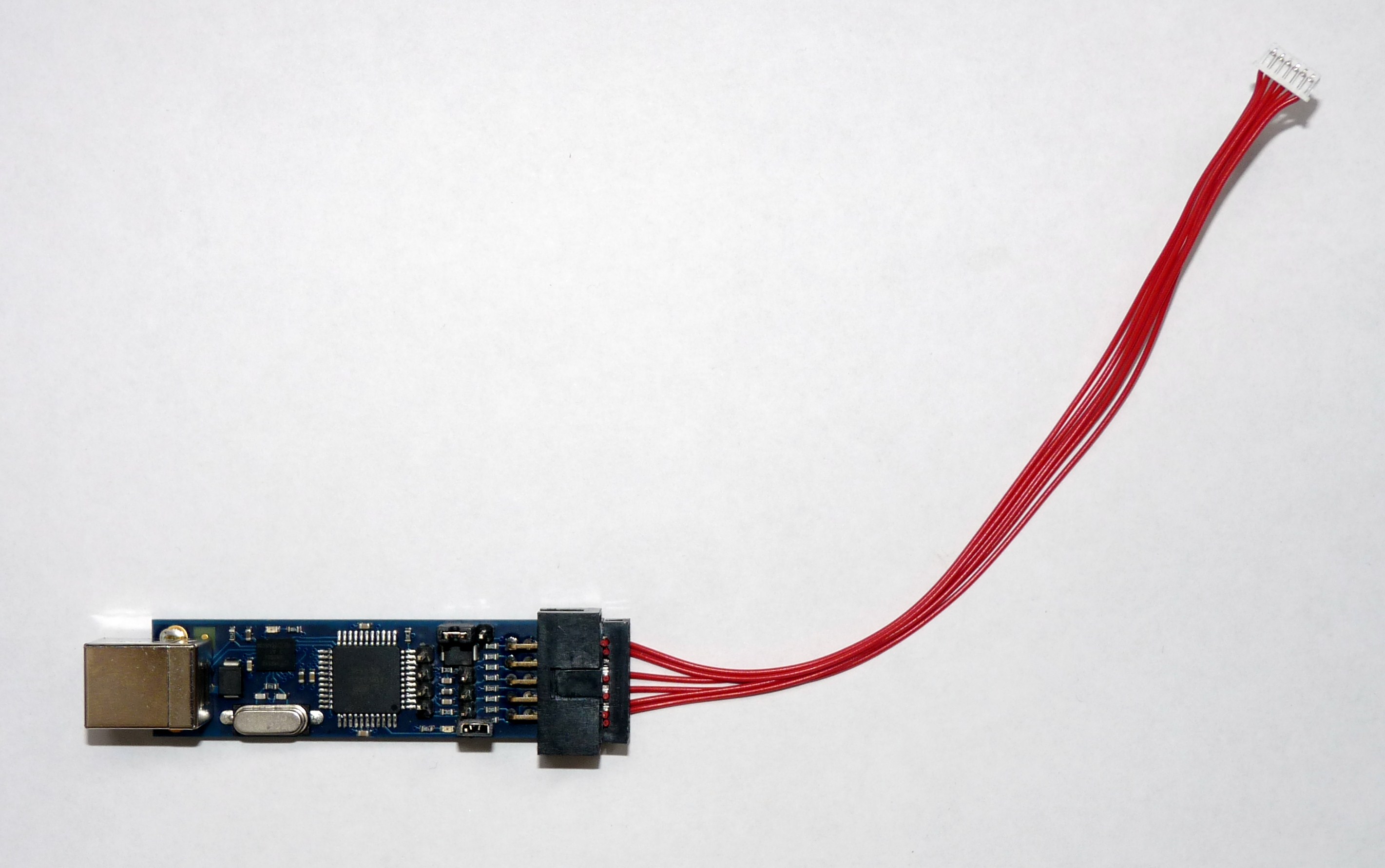
The cable has to be configured as following (hw-ngblc-4mini-r2 is using Picoblade also called Molex connector)
| Signal | 10pin female connector | 6pin female connector | 6pin Picoblade (Molex) connector |
| MOSI | 1 | 4 | 3 |
| VCC | 2 | 2 | 1 |
| RESET | 5 | 5 | 5 |
| SCK | 7 | 3 | 4 |
| MISO | 9 | 1 | 2 |
| GND | 10 | 6 | 6 |
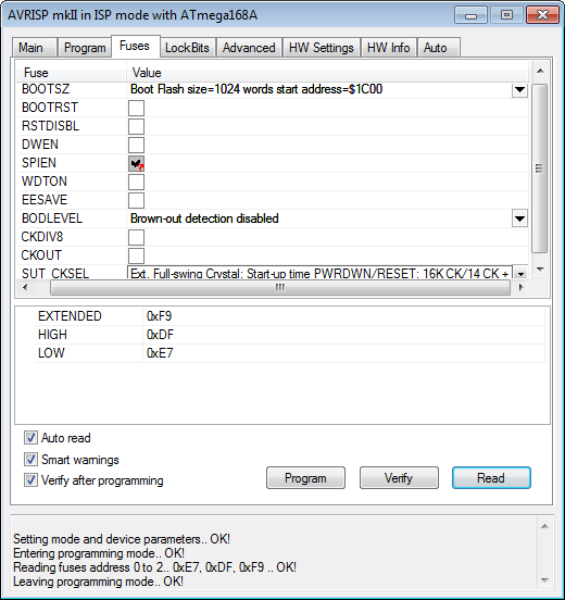
Fuses of the ATmega168 and ATmega168A
Programming and Fuses in Atmel Studio 6
Go to Tools > Device Programming Select the correct Tool and Device.
Check the device signature that this belongs to the selected controller.
Go to Fuses and select:
| BODLEVEL | 2V7 |
| CKDIV8 | deactivated |
| SUT_CKSEL | EXTCLK_6CK_14CK_4MS1 |
Go to Memories
Erase device before programming must be selected. Select the right hex file and Program and Verify.
SimonK Firmware
It is also possible to use the SimonK firmware on the NGBLC. A modified version of the SimonK’s firmware is available in NGOS >= Version 0.68. We need to modify the SimonK source code as our NGBLC-4mini uses an Atmega168.
You need to be carefully, because you have to use different fuses:
Flash firmware with AVRdude: sudo avrdude -p m168 -c avrispmkII -P usb -U ngblc-simonk-M1.hex -u -U lfuse:w:0xd0:m -U hfuse:w:0xdd:m -U efuse:w:0xf9:m (for motor 1)
Read out fuses with AVRdude (ignore efuses, they’ll be wrong): sudo avrdude -p m168 -c avrispmkII -P usb -n -v
After flashing your BLC should react like this:
- After power on the green and red Led’s are on and you should hear three increasing beeps from motor 1, with a delay then from motor 2 and so on to have a clear signal from each motor and not all at the same time.
- If not, or if you hear only some beeps, the FET pinout may be incorrect or one or more FETs may be broken. Repetitive clicking can also indicate that the pinout is incorrect and causing continuous brown-out resets.
- Now, when the FC starts, with the first valid I2C signal you should hear a fourth beep from each motor (without a delay between the motors) indicating that the ESC is armed and the red Led will switch off.
If the NGBLC-4mini power supply is always on and not switched off/on from the FC (various options), you have to protect the discharging of your battery on your own. To assist you with that: If the FC is switched of, you will hear a periodically beep from each motor and the red Led’s will blink. That signal is generated from I2C signal loss.
Here is a summary of beep sequences in case of trouble:
f1 f2 f3: Regular startup with nothing special detected

f3 f1: Voltage brown-out bit was set (MCU voltage dropped below 2.7V/4.0V)

f4: External reset (via the reset pin, as in after programming)

looping f1 f1 f3 f3: Watchdog reset (previous execution locked up)

looping beeps (8) of f2 or f4: Unknown (beeps out all MCUCSR bits, LSF)
Testing
When you have successfully flashed the controllers and the NGBLC is connected to FC and all motors are found in “Show Devices” BL-Ctrl Style (Motor 1), BL-Ctrl Style (Motor 2), BL-Ctrl Style (Motor 3), BL-Ctrl Style (Motor 4).
Then you are ready to start the motors the first time. You can do that by console or via the receiver. Make sure that you have not attached the props the first time. Note that you cannot use the LaboratoryPowerSupply to starting the motors because of the hight current requirement, this may only possible with a real battery that is connected.
# set controller none
Activated controller 'none'
Setting string 'controller' to 'none'
# set HW.HAL blc
Activated propeller HAL 'blc'
Setting 'HW.HAL' to HAL 'blc'
# set BLC4 40
Setting integer byte 'BLC4' to '40'
# enable motors
Activated controller and actors
# disable motors
Deactivated controller and actors
Partlists
- The NGBLC r0 partlist: NGBLC-4mini-r0
- The NGBLC r2 partlist: NGBLC-4mini-r2